Reference Manual
00809-0100-4004, Rev BA
August 2010
2-15
Rosemount 8800D
Cable Gland If you are using cable glands instead of conduit, follow the cable gland
manufacturer’s instructions for preparation and make the connections in a
conventional manner in accordance with local or plant electrical codes. Be sure to
properly seal unused ports to prevent moisture or other contamination from
entering the terminal block compartment of the electronics housing.
Grounding the
Transmitter Case
The transmitter case should always be grounded in accordance with national
and local electrical codes. The most effective transmitter case grounding
method is direct connection to earth ground with minimal impedance.
Methods for grounding the transmitter case include:
• Internal Ground Connection: The Internal Ground Connection screw
is inside the FIELD TERMINALS side of the electronics housing. This
screw is identified by a ground symbol ( ), and is standard on all
Rosemount 8800D transmitters.
• External Ground Assembly: This assembly is included with the
optional transient protection terminal block (Option Code T1). The
External Ground Assembly can also be ordered with the transmitter
(Option Code V5) and is automatically included with certain hazardous
area approvals.
NOTE
Grounding the transmitter case using the threaded conduit connection may
not provide a sufficient ground. The transient protection terminal block (Option
Code T1) does not provide transient protection unless the transmitter case is
properly grounded. See “Transient Terminal Block” on page 2-26 for transient
terminal block grounding. Use the above guidelines to ground the transmitter
case. Do not run the transient protection ground wire with signal wiring as the
ground wire may carry excessive current if a lightning strike occurs.
Wiring Procedure The signal terminals are located in a compartment of the electronics housing
separate from the flowmeter electronics. Connections for a HART-based
communicator and a current test connection are above the signal terminals.
Figure 2-11 illustrates the power supply load limitations for the flowmeter.
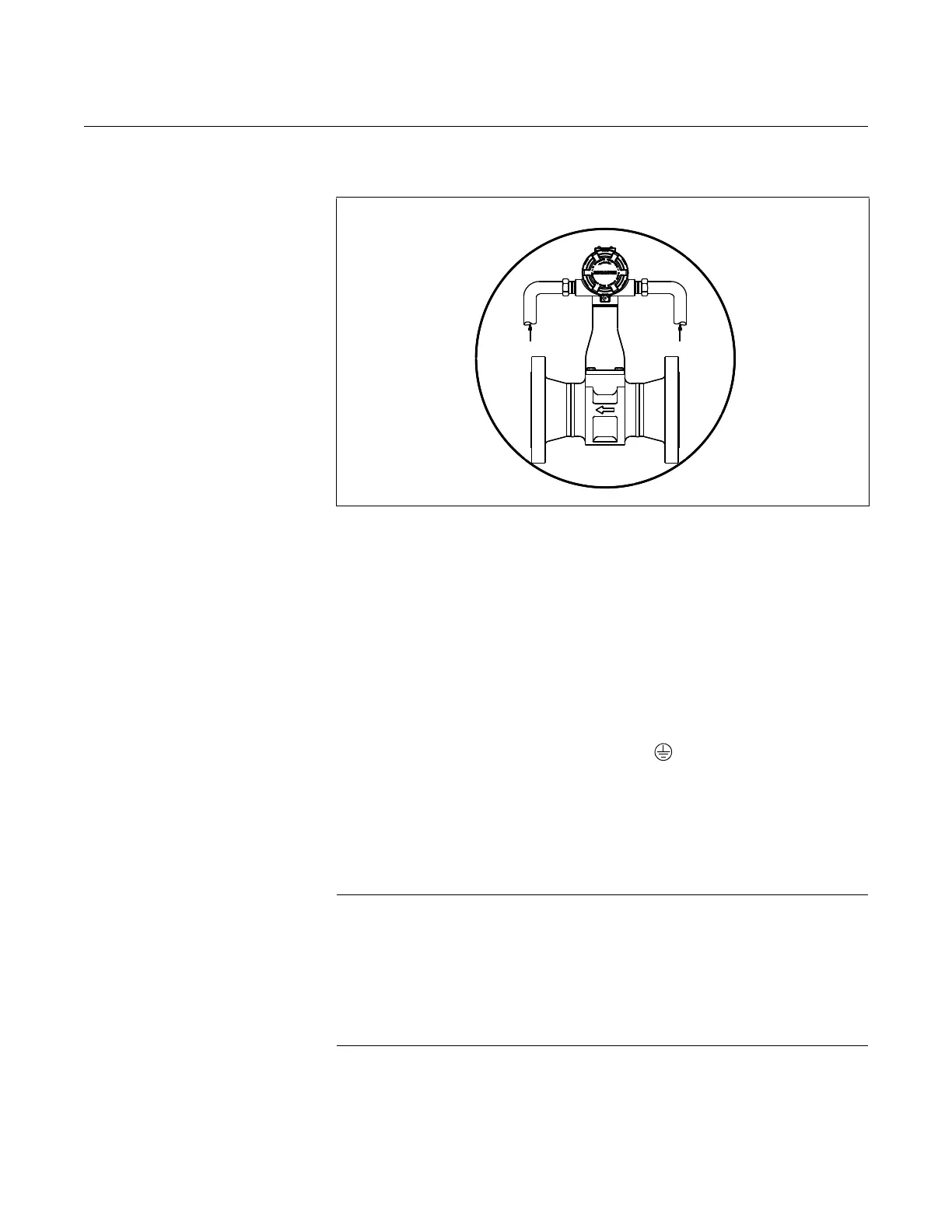
Figure 2-10. Proper Conduit Installation with Rosemount 8800D

 Loading...


