Reference Manual
00809-0100-4004, Rev BA
August 2010
5-5
Rosemount 8800D
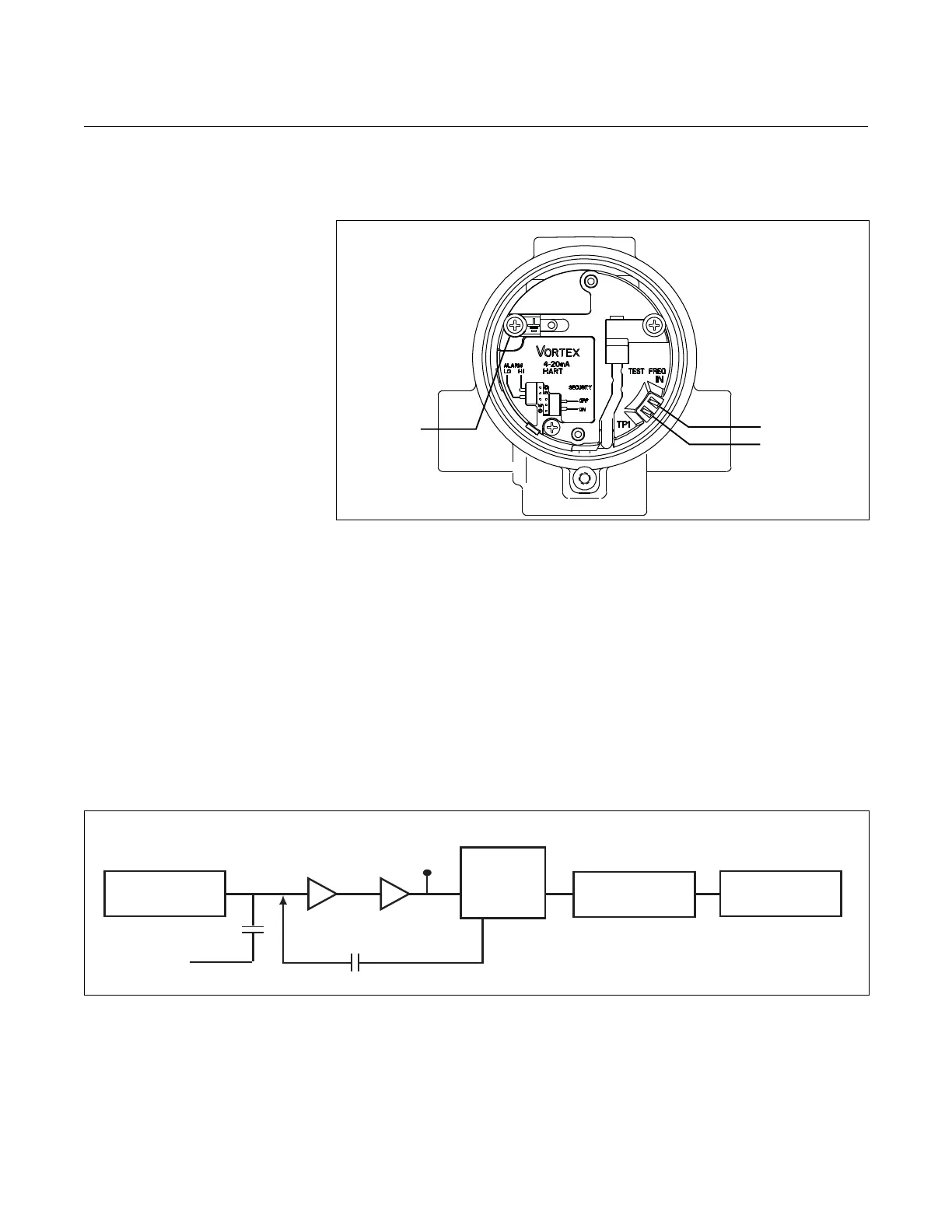
Electronics Test Points As shown in Figure 5-1, there are several test points located on the
electronics.
The electronics is capable of internally generating a flow signal that may be
used to simulate a sensor signal to perform electronics verification with a
Handheld Communicator or AMS interface. The simulated signal amplitude is
based on the transmitter required minimum process density. The signal being
simulated can be one of several profiles – a simulated signal of constant
frequency or a simulated signal representative of a ramping flow rate. The
electronics verification procedure is described in detail in Appendix C:
Electronics Verification. To verify the electronics, you can input a frequency on
the “TEST FREQ IN” and “GROUND” pins to simulate flow via an external
signal source such as a frequency generator. To analyze and/or troubleshoot
the electronics, an oscilloscope (set for AC coupling) and a Handheld
Communicator or AMS interface are required. Figure 5-2 is a block diagram of
the signal as it flows from the sensor to the microprocessor in the electronics.
Figure 5-1. Electronics Test Points
Figure 5-2. Signal Flow
Sensor
Charge
Amplifier
Amplifier/
Low Pass
Filter
External
Test
Frequency
Input
TP1
Digital Filter
Microprocessor
A-to-D
Converter
Internal
Frequency
Generator

 Loading...


