Reference Manual
00809-0100-4004, Rev BA
August 2010
Rosemount 8800D
5-18
4. Manually push down on the sensor by applying equal pressure for
engagement onto the post.
5. Screw the sensor nut into the sensor cavity. Tighten the nut
with a 1
1
/8-in. (28 mm) open end torque wrench to 32 ft-lbs (43.4 N-m)
(50 ft-lbs (67.8 N-m) for ANSI 1500 meter body). (Use a
3
/4-in. (19
mm) open end wrench for 3- and 4-in. [80 and 100 mm] SST wafers).
Do not overtighten the sensor nut.
6. Replace the support tube.
7. Tighten the four bolts that anchor the support tube in place
with a
7
/16-in. (11 mm) open end wrench.
8. Install the flowmeter electronics housing. See Replacing the
Electronics Housing on page 5-12.
Remote Electronics
Procedure
If the Rosemount 8800D electronics housing is mounted remotely, some
replacement procedures are different than for the flowmeter with integral
electronics. The following procedures are exactly the same:
• Replacing the Terminal Block in the Housing (see page 5-9).
• Replacing the Electronics Boards (see page 5-10).
• Replacing the Sensor (see page 5-14).
To disconnect the coaxial cable from the meter body and electronics housing,
follow the instructions below.
Disconnect the Coaxial Cable at the Meter
1. Remove the access cover on the meter body support tube if present.
2. Loosen the three housing rotation screws at the base of the meter
adapter with a
5
/32-in. hex wrench by turning the screws clockwise
(inward) until they clear the bracket.
3. Slowly pull the meter adapter no more than 1.5-in. (40 mm) from the
top of the support tube.
4. Loosen and disconnect the sensor cable nut from the union using
a
5
/16-in. open end wrench.
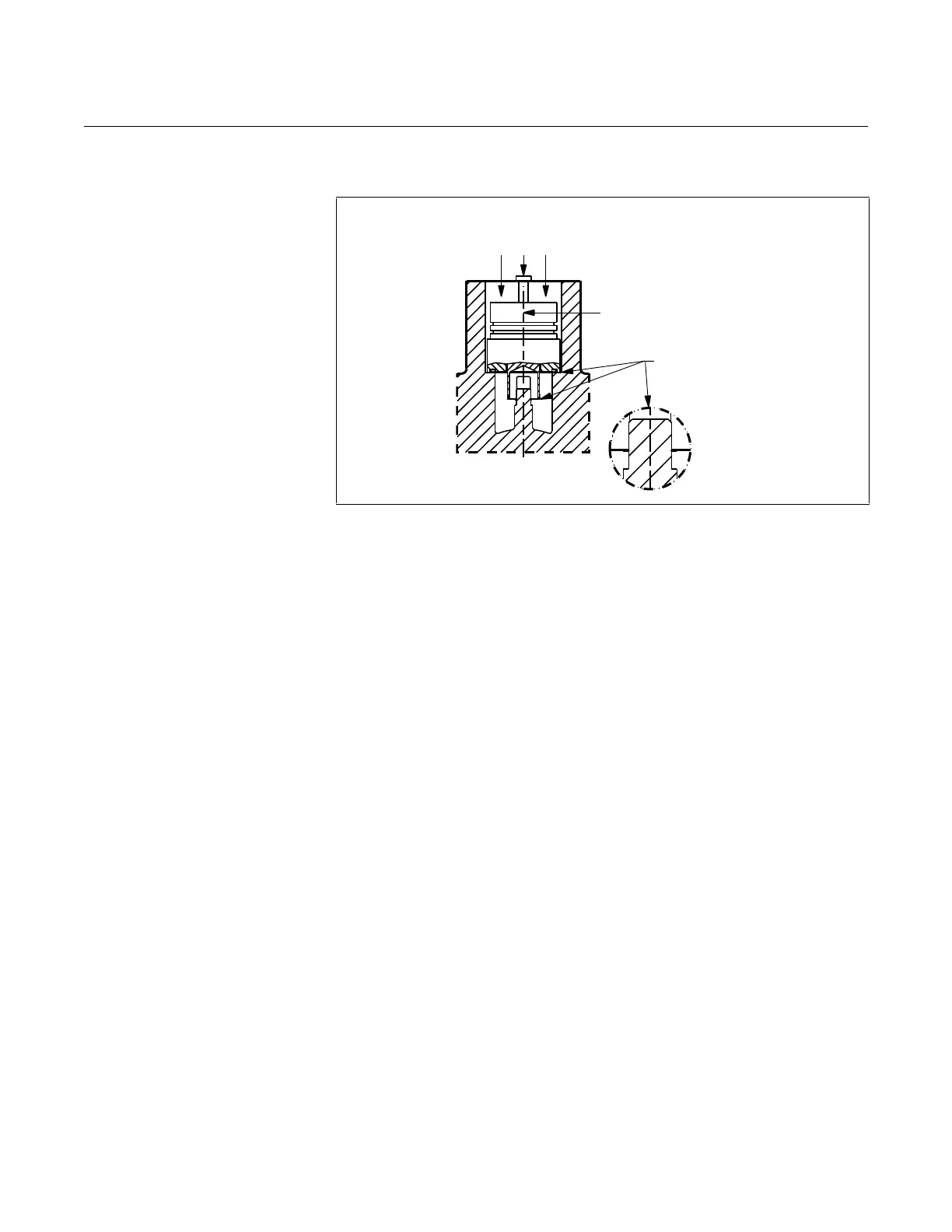
Figure 5-12. Sensor Installation – Applying Force
Pressure
Sensor centerline must be
aligned with flowmeter
centerline
Sensor properly
seated
Apply Force
With Hand Until
Sensor is Seated

 Loading...


