Reference Manual
00809-0100-4004, Rev BA
August 2010
Rosemount 8800D
5-2
TROUBLESHOOTING
TABLES
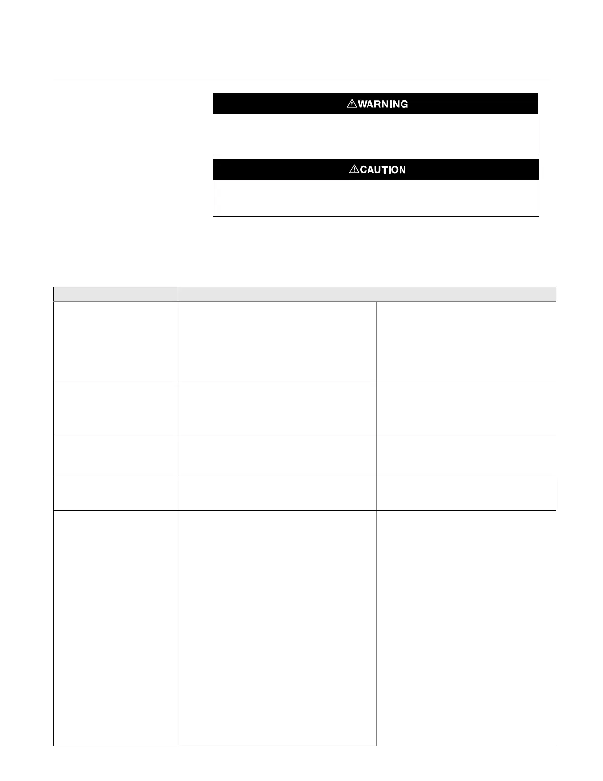
The most common problems experienced by users of the Rosemount 8800D
are listed in “Troubleshooting Tables” on page 5-2 along with potential causes
of the problem and suggested corrective actions. See the Advanced
Troubleshooting section if the problem you are experiencing is not listed here.
Failure to follow these installation guidelines could result in death or serious injury:
• Make sure only qualified personnel perform the installation.
The sensor cavity could contain line pressure if an abnormal failure has occurred inside
the meter body. Depressurize flow line before removing the sensor nut.
Symptom Corrective Action
Communication
problems with
HART-based Communicator
• Check for a minimum of 10.8 Vdc at transmitter
terminals
• Check communications loop with HART-based
communicator.
• Check for loop resistor (250 to 1000 ohms).
• Measure loop resistor value (R
loop
) and source power
supply voltage (V
ps
). Check that [V
ps
- (R
loop
x 0.024)] >
10.8 Vdc.
• Check for transmitter in multidrop mode.
• Check for transmitter in burst mode.
• Remove pulse connection if you have a three wire
pulse installation.
• Replace electronics.
Incorrect 4–20 mA Output
• Check for minimum 10.8 Vdc at transmitter terminals.
• Check URV, LRV, Density, Special Units, LFC–compare
these inputs with the sizing program results. Correct
configuration.
• Perform 4–20 mA loop test.
• Check for corrosion on terminal block.
• Replace electronics if necessary.
• Refer to “Advanced Troubleshooting” on page 5-3.
• See Appendix C: Electronics Verification for
electronics verification procedure.
Incorrect Pulse Output
• Check that 4–20 mA output is correct.
• Check pulse counter specifications.
• Check pulse mode and scaling factor. (Make sure
scaling factor is not inverted).
• Perform pulse test.
• Select pulse scaling so that pulse output is less
than 10,000Hz at URV.
Error Messages on HART-based
Communicator
• See alphabetical listing in the Error Messages Table for
the communicator starting on page 5-3.: Diagnostic
Messages
Flow in Pipe, No Output Basics
• Check to make the sure that the meter is installed with
the arrow in the direction of process flow.
• Perform basic checks for Incorrect 4–20 mA Output
Problem (see Incorrect 4–20 mA Output).
• Check and correct configuration parameters in this
order:
Process Config - transmitter mode, process fluid,
fixed process temperature, density/density ratio (if
required), reference K-factor, flange type, mating pipe
ID, variable mapping, PV unit, range values - (URV,
LRV), PV damping, auto filter adjust, pulse mode and
scaling (if used).
• Check sizing. Make sure flow is within measurable
flow limits. Use Instrument Toolkit for best sizing
results.
• Refer to “Advanced Troubleshooting” on page 5-3.
• See Appendix C: Electronics Verification for
electronics verification procedure.
Electronics
• Run a self test with a HART-based interface tool.
• Using sensor simulator, apply test signal.
• Check configuration, LFC, trigger level, STD vs.
actual flow units.
• Replace electronics.
Application Problems
• Calculate expected frequency (see Appendix C:
Electronics Verification). If actual frequency is
the same, check configuration.
• Check that application meets viscosity and
specific gravity requirements for the line size.
• Recalculate back pressure requirement. If
necessary and possible, increase back
pressure, flow rate, or operating pressure.
Sensor
• Check torque on sensor nut (32 ft-lb). For 1-8
inch meter body with ANSI 1500 flanges torque
on sensor nut should be 50 ft-lbs.
• Inspect coaxial sensor cable for cracks. Replace
if necessary.
• Check that sensor impedance at process
temperature is > 1 Mega-Ohm (will function
down to 0.5 Mega-Ohms). Replace sensor if
necessary (“Replacing the Sensor” on
page 5-13).
• Measure sensor capacitance at SMA connector
(115-700pF).

 Loading...


