EasyManuals Logo

Rosemount 8800D Series User Manual

Rosemount 8800D Series
172 pages
To Next Page IconTo Next Page
To Previous Page IconTo Previous Page
Page #30 background imageLoading...
Page #30 background image
Reference Manual
00809-0100-4004, Rev BA
August 2010
Rosemount 8800D
2-20
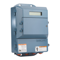
Remote Electronics If you order one of the remote electronics options (options R10, R20, R30, or
RXX), the flowmeter assembly will be shipped in two parts:
1. The meter body with an adapter installed in the support tube and an
interconnecting coaxial cable attached to it.
2. The electronics housing installed on a mounting bracket.
Mounting
Mount the meter body in the process flow line as described earlier in this
section. Mount the bracket and electronics housing in the desired location.
The housing can be repositioned on the bracket to facilitate field wiring and
conduit routing.
Cable Connections
Refer to Figure 2-16 and the following instructions to connect the loose end of
the coaxial cable to the electronics housing. (See “Remote Electronics
Procedure” on page 5-18 if connecting/disconnecting the meter adapter to the
meter body.)
Figure 2-15. 4–20 mA and Pulse Wiring with Electronic Totalizer/ Counter
R
L
250
+
Test
Ammeter
+
-
Pulse
Counter

Table of Contents

Questions and Answers:

Question and Answer IconNeed help?

Do you have a question about the Rosemount 8800D Series and is the answer not in the manual?

Rosemount 8800D Series Specifications

General IconGeneral
TypeVortex Flow Meter
Measurement PrincipleVortex Shedding
Operating Temperature-40 to 185°F (-40 to 85°C)
Storage Temperature-40 to 185°F (-40 to 85°C)
Communication ProtocolsFOUNDATION Fieldbus
Material316 stainless steel
Fluid TypeLiquid, Gas, Steam
Line Size1/2 to 8 inches (15 to 200 mm)
ApprovalsATEX, IECEx, CSA, FM
Output Signal4-20 mA
Process ConnectionFlanged, Wafer, Threaded
Electrical ConnectionM20
Protection RatingIP66
Mounting StyleWafer, Flanged

Related product manuals