ROTAX 125 MAX evo, Junior MAX evo, Mini MAX evo, Micro MAX evo
2.1.3. Installation and connection of the RAVE control unit (125 MAX only)
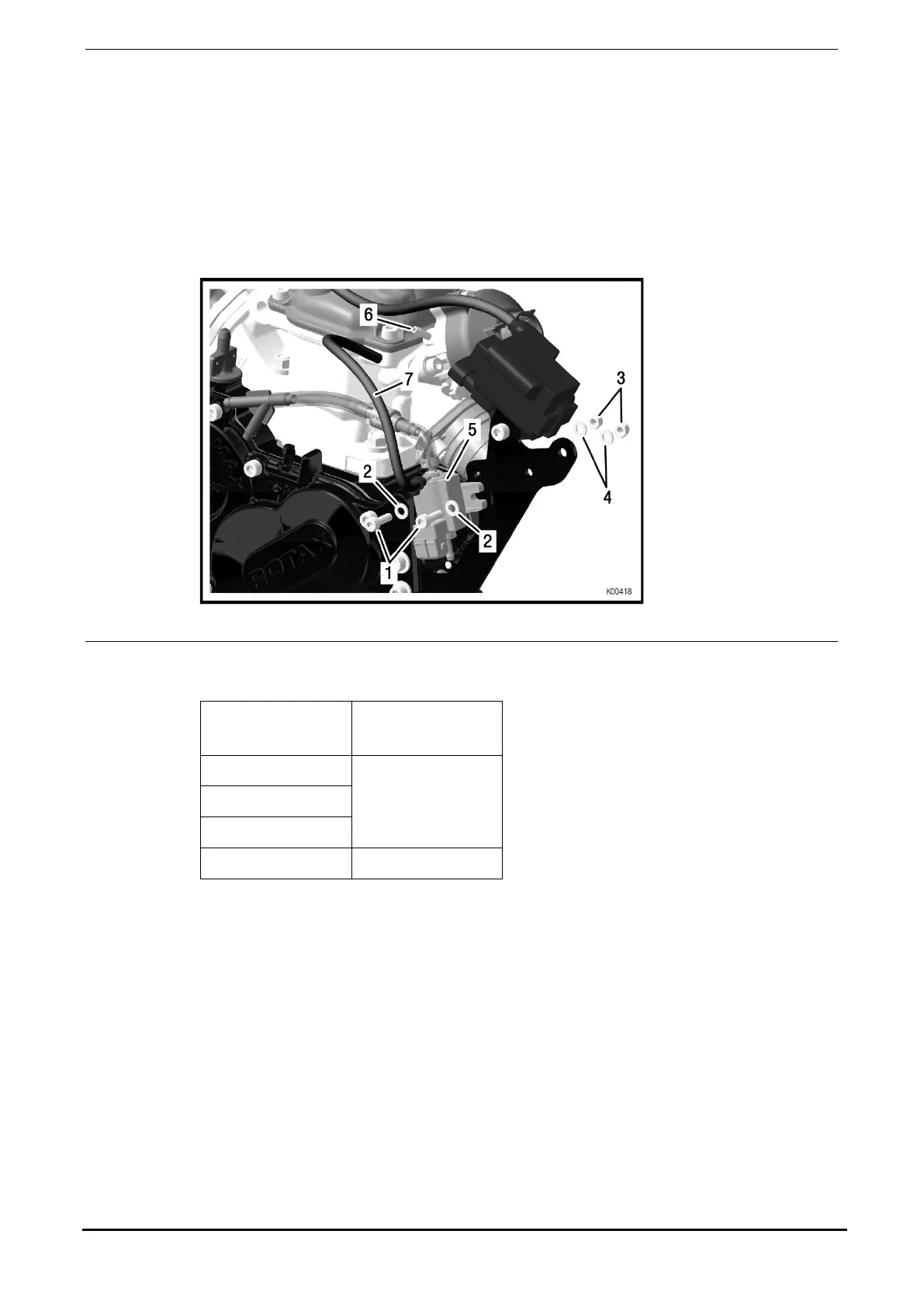
See Fig. 4.
The RAVE control unit is delivered and offered as complete part.
Install RAVE control unit with 2 screws M5x16 (pos. 1) and washers (pos. 2) on the
front and 2 nuts M5 (pos. 3) with washers (pos. 4) on the rear of the support bracket.
Fasten the control line of the exhaust valve (black hose, pos. 7) to the valve rod
housing (pos. 6).
Fig. 4
2.1.4. Installation of the ECU
Engine
ECU part no.
125 MAX
666814
125 Mini MAX
125 Micro MAX
125 Junior MAX 666812
Install the ECU (pos. 1) with rubber buffer (pos. 3), washers (pos. 4) and nuts (pos.
5) onto the support bracket. Make sure that the sleeve (pos. 2) is screwed in with
the ECU.
Note: The position of the ECU should ensure that the plug connections of the ECU and the
ignition coil are aligned.
Seite/page 53/98
Ausgabe/Edition 11/2014

 Loading...


