EasyManuals Logo

Rotax 912 i series Service Manual

Rotax 912 i series
168 pages
To Next Page IconTo Next Page
To Previous Page IconTo Previous Page
Page #73 background imageLoading...
Page #73 background image
BRP-Rotax
MAINTENANCE MANUAL LINE
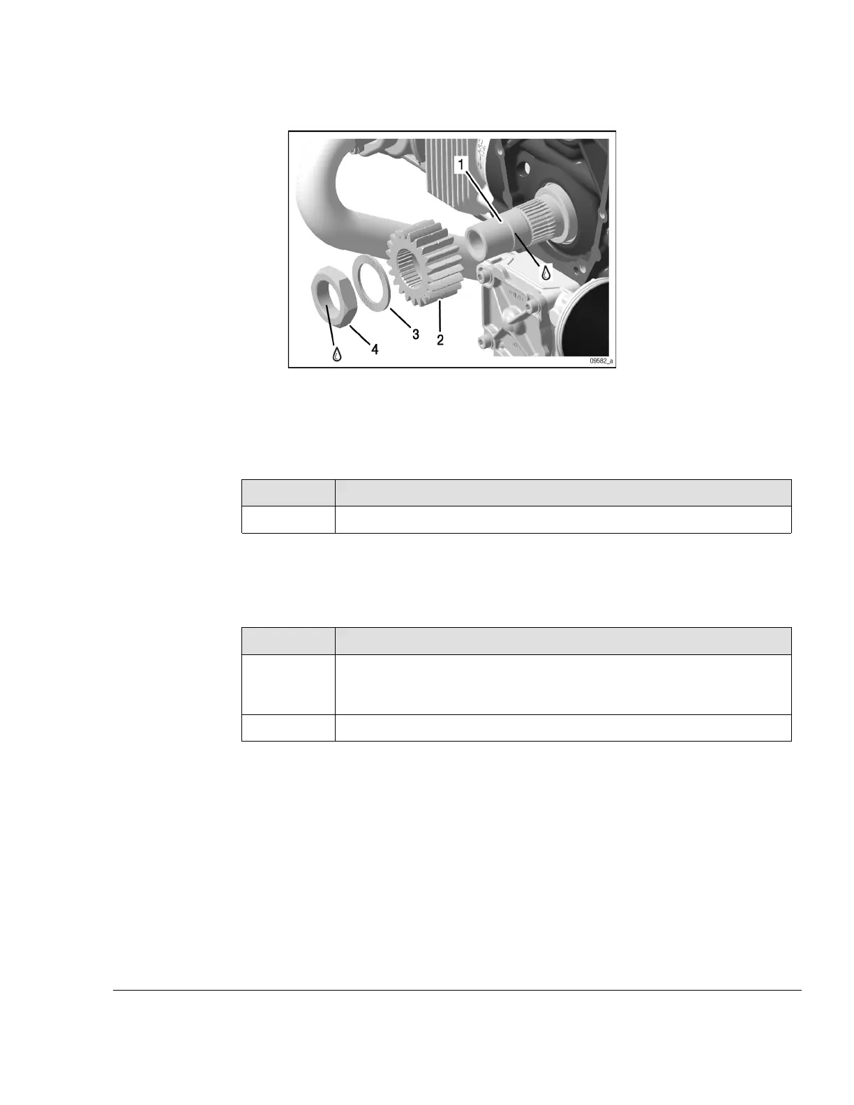
Figure 5.6
1
Crankshaft (power take off side)
2
Drive gear
3 Friction washer VS-30 4 Hex. nut
Step
Procedure
1
Push the drive gear onto the crankshaft.
NOTE
Due to limited tolerances, it may be difficult to push the drive gear onto the end of
the crankshaft. If necessary, turn it and push it on in another position.
Step
Procedure
2
Secure the hex. nut M30x1.5 with LOCTITE 648 and screw it counter
clockwise left hand threads onto the crankshaft along with the friction
washer VS-30. Tightening torque 200 Nm (147 ft.lb.).
3 Inspect the run out.
Effectivity: 912 i Series
Edition 2/Rev. 0
05–50–00
Page 7
September 01/2018

Table of Contents

Other manuals for Rotax 912 i series

Questions and Answers:

Question and Answer IconNeed help?

Do you have a question about the Rotax 912 i series and is the answer not in the manual?

Rotax 912 i series Specifications

General IconGeneral
Number of Cylinders4
Max Power100 hp (73.5 kW)
Max Power Output RPM5800 rpm
Ignition SystemDual electronic ignition
Oil SystemDry sump, forced lubrication with separate oil tank
Reduction Gear Ratio2.43:1
TBO2000 hours
Engine Type4-stroke, horizontally opposed
Displacement1352 cm³
Bore x Stroke84 mm x 61 mm
Max Torque128 Nm
Fuel TypeAvgas 100LL or unleaded automotive gasoline
Fuel SystemElectronic fuel injection
Cooling SystemLiquid/air-cooled

Related product manuals