41
Press [OK] to save the point
A negative value in the Sta field means the opposite direction along the defined bearing line.
A negative value in the O/S field is for the left-hand side of the bearing line
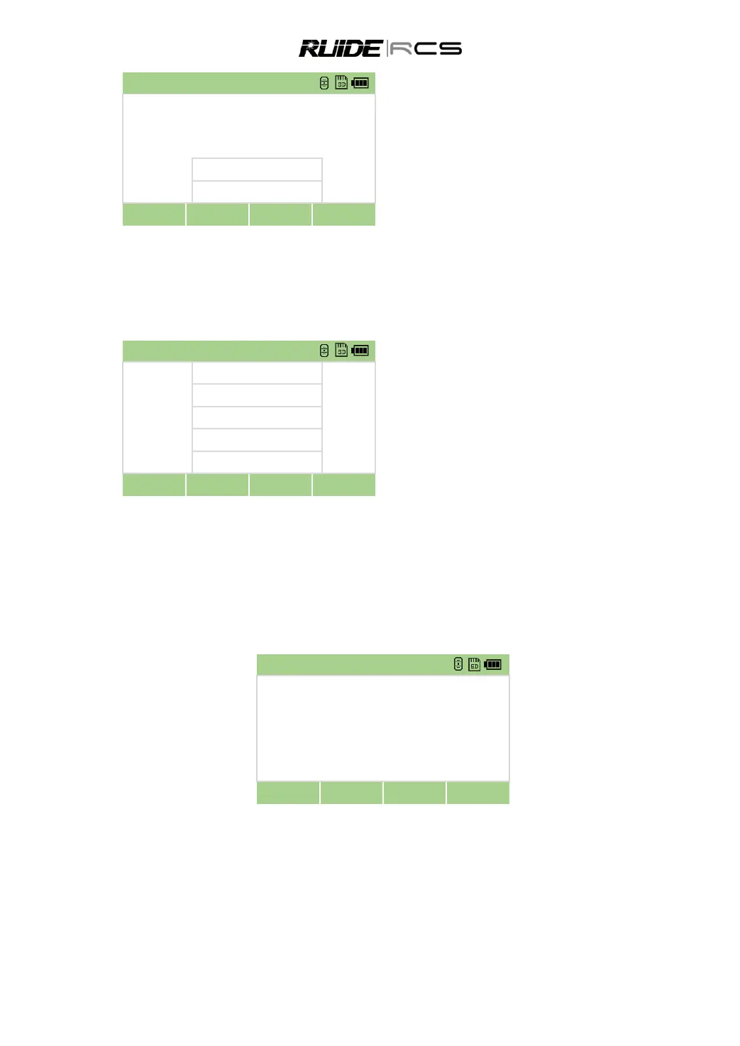
9.5 INPUT COORDINATES MANUALLY
In Cogo menu press key [5] to manually enter
the XYZ coordinates.
Enter the coordinate and point name, code.
Press[OK] to save the point
10. ROADS
This program enables you to easily define a line or curve or spiral as a reference for measurements and
stake outs. It supports chainages, as well as incremental stake-outs and offsets.
Before starting road design and stake-out, user should set job, station, and orientation first.
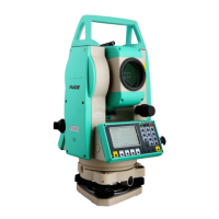
10.1 DEFINE HZ ALIGNMENT
Horizontal alignment consists of the following elements: start point, line, curve and spiral.
To define a horizontal alignment, user should first input the detailed information (Chain, N, E coordinate) of
start point.
The element of start point consists of the start chainage and E, N coordinate of start point. Enter these
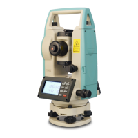
details, and press [ENT] to display the main line inputting screen.
The screen displays: current chainage, the azimuth angle of the tangent on the chainage, and the
function key of the establishing new line. The system provides three functions: defining line,