Do you have a question about the Ruide RCS and is the answer not in the manual?
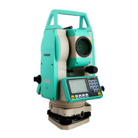
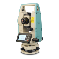
Identification of all physical components of the instrument.
Description of the instrument's main display screen and its elements.
Explanation of the instrument's keypad layout and button functions.
Details on the functions assigned to the soft keys.
Glossary of symbols and abbreviations used throughout the manual.
Accessing common settings quickly using the star key.
Instructions for safe unpacking and proper storage of the instrument.
Step-by-step guide for setting up the instrument on a tripod.
Guidance on battery charging, usage, and maintenance for optimal performance.
Information on selecting and using reflectors for measurements.
Procedures for securely attaching and detaching the instrument from its base.
Adjusting the eyepiece for clarity and aligning the instrument with the target.
Explanation of different modes for data input on the instrument.
Methods for precisely leveling the instrument using its built-in sensor.
Important safety and operational precautions before distance measurement.
Configuration settings for the Electronic Distance Measurement (EDM) module.
Utilizing the dedicated Hot Key for quick access to essential functions.
Procedure to input and set the height of the measurement target.
Setting atmospheric conditions for accurate distance corrections.
Choosing predefined target configurations for efficient measurements.
Adding descriptive notes to recorded measurement points.
Initiating a new survey session after all settings are confirmed.
Performing precise angle measurements using the instrument's functions.
Function to reset the horizontal angle reading to zero.
Manually inputting a specific horizontal angle value.
Measuring in both Face-1 and Face-2 for enhanced accuracy.
Holding the current horizontal angle reading.
Accessing and loading previously saved job files.
Procedure for creating and configuring a new project job.
Removing unwanted job files from the instrument's memory.
Viewing details and summary of existing job files.
Establishing the instrument's position using known coordinate points.
Detailed steps for station setup using known coordinate data.
Orienting the instrument using backsight by azimuth angle input.
Determining station position by measuring to multiple known points.
Setting the instrument's station point without prior coordinate data.
Calculating the instrument's elevation by transferring known point heights.
Verifying and re-establishing the backsight orientation.
Guiding stakeout operations based on specified angles and distances.
Performing stakeout tasks using predefined XYZ coordinates.
Stakeout along a line divided into multiple segments.
Stakeout operations relative to a specified reference line.
Using the guide light feature for accurate stakeout alignment.
Measuring horizontal and vertical offsets relative to a distance.
Measuring horizontal and vertical offsets relative to an angle.
Procedures for using the two-prism pole for measurements.
Extending a line using horizontal angle offset calculations.
Manually entering horizontal distance when direct measurement is difficult.
Calculating the coordinates of a corner based on measured points.
Measuring the center and edges of a column for its geometry.
Extending slope distance measurements by entering values.
Defining a reference line using two points for stakeout.
Measuring distances and offsets along a defined arc.
Measuring distances between points without direct line of sight.
Measuring radial distances from the instrument to multiple points.
Measuring distances between consecutive points in a sequence.
Determining elevation differences remotely using measurements.
Defining and measuring on a vertical plane using two points.
Defining and measuring on a slope plane using three points.
Performing inverse calculations between coordinate points.
Calculating distance and angle between two input points.
Calculating angles defined by three points in sequence.
Calculating coordinates by direct measurements (Azimuth & Distance).
Calculating coordinates using Azimuth, Horizontal Distance, and Vertical Distance.
Storing calculated points based on baseline and offsets.
Computing the area and perimeter of a closed lot.
Calculating coordinates based on a defined line and offsets.
Defining a line by inputting a base point and azimuth.
Calculating a line's azimuth and parameters using two points.
Manually entering point coordinates (XYZ) and associated data.
Defining the horizontal geometric layout of a road alignment.
Defining a straight line segment within the road alignment.
Defining a circular curve segment within the road alignment.
Modifying previously entered horizontal alignment data.
Importing horizontal alignment data from an external source.
Removing horizontal alignment data from the instrument's memory.
Defining the vertical geometric profile of a road alignment.
Performing stakeout operations for defined road alignments.
Viewing, editing, and managing raw measurement data files.
Viewing, editing, and managing calculated coordinate data.
Displaying recorded data organized by the station point.
Managing lists of point names and feature codes.
Transferring data to and from the instrument via SD card.
Checking memory status and formatting instrument storage.
Procedures for checking and adjusting the plate vial for leveling.
Checking the circular vial for proper leveling after plate vial adjustment.
Checking and adjusting the reticle for precise alignment.
Ensuring the line of sight is perpendicular to the horizontal axis.
Compensating for errors in the vertical angle reading due to index difference.
Adjusting vertical index difference and setting the vertical zero datum.
Checking and adjusting the instrument's optical plummet.
Checking and adjusting the instrument's constant for distance measurements.
Verifying the alignment between the line of sight and the EDM photoelectric axis.
Adjusting the tribrach leveling screws for instrument stability.
Checking and adjusting components associated with reflector usage.
Format of raw data transmitted from the total station to a PC.
Format of coordinate data uploaded or downloaded from the instrument.
Format of the code list used for quick code function.
Data format specification for horizontal line transmission.
Methods for entering road alignment data manually or via PC.
Formulas and calculations for road alignment elements like curves and transitions.
| Brand | Ruide |
|---|---|
| Model | RCS |
| Category | Measuring Instruments |
| Language | English |