MCA-C3 Test Procedure
Page 34 of 77
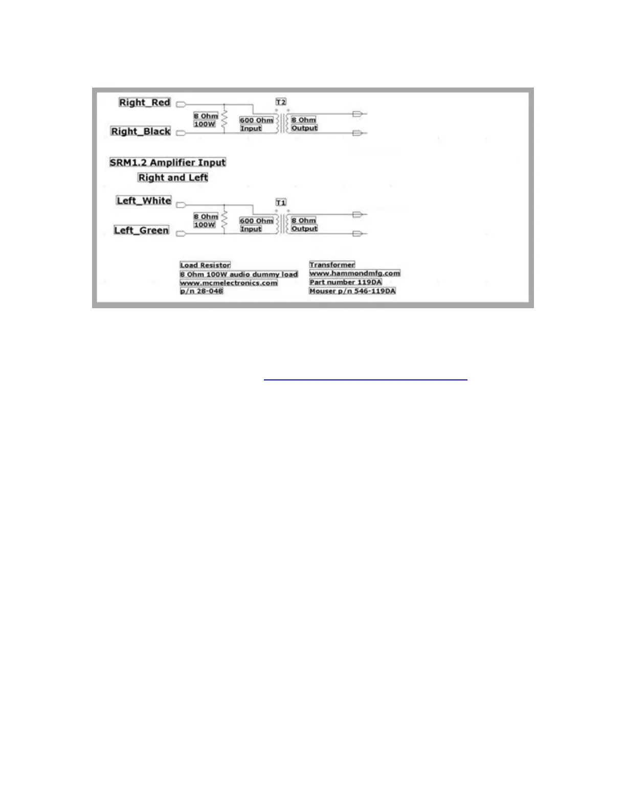
Speaker Isolation Fixture
26. Once again, the RCK and all RSS are powered by a 12V 1.5A power pack.
Connect the ground, negative, pin of each power pack together.
27. Continue by performing the “Start MCA-C3 Tests using 240V AC” section.
Note: There is a diagram of the RSS, RCK, Speaker Selector
Connections and Speaker Output isolation fixture in the
end of the Test Procedure.
Oscilloscope
CH1 and CH2