MCA-C3 Test Procedure
Page 33 of 77
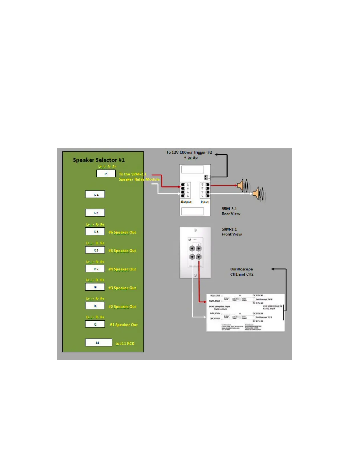
21. Build 7 Speaker cables that connect between each zone of the Speaker
Selector and each zone of the MCA-C3.
22. Connect J1 Speaker Selector to Zone 1 Speaker Output MCA-C3.
Connect J6 Speaker Selector to Zone 2 Speaker Output MCA-C3.
Connect J9 Speaker Selector to Zone 3 Speaker Output MCA-C3.
Connect J12 Speaker Selector to Zone 4 Speaker Output MCA-C3.
Connect J15 Speaker Selector to Zone 5 Speaker Output MCA-C3.
Connect J18 Speaker Selector to Zone 6 Speaker Output MCA-C3.
23. Connect Speaker Selector J3 to the SRM-2.1 and the SRM 2.1
to the Speaker Isolation fixture and set of Speakers.
The Output of the Speaker Isolation Fixture will connect to the
second oscilloscope channel 1 and 2.
Note: This diagram was not part of the
MCA-C5 test procedure 1.7 but can be added if needed.
24. Connect a 3.5mm mono jack Positive tip to the SRM2.1 trigger input.
25. Look on next page for larger picture of Speaker Isolation Fixture.
Speaker Isolation Fixture