MCA-C3 Test Procedure
Page 32 of 77
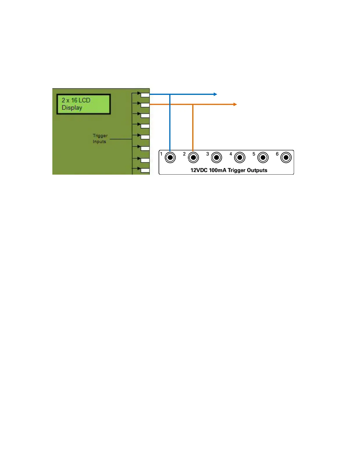
14. Connect 12V Trigger 1 from MCA-C3 to Trigger 1 IR Switcher and
MiniJack 1 of SGTF. (MCA-C3 will control 100Hz or 10Khz signal)
Connect 12V Trigger 2 from MCA-C3 to Trigger 2 IR Switcher and
SRM-2.1 Trigger input (This controls Speaker Output or Oscilloscope)
Note: Trigger 1 MCA-C3 off selects 100Hz signal from SGTF
on selects 10KHz signal from SGTF
Trigger 2 MCA-C3 off connects Oscope to MCA-C3 Speaker Out.
on connects Speakers to MCA-C3 Speaker Out.
15. Ensure AC power is applied to all 12V 1A power packs.
16. Connect a USB A-to-B cable from your PC to the MCA-C3 front panel USB
port.
17. Connect an RJ45 patch cable from the 4 Port Ethernet Switch connected to
your computer to the Ethernet Port of the MCA-C3.
18. Connect a cable from the RCK J11 to this Speaker Selector J4.
This is Zone Speaker Outputs 1 – 8.
19. Use a female header that plugs into the male header of RCK J11.
For the female header solder each Cat5e wire as follows.
Pin 1 to Brown, Pin 2 to Brown/White, Pin 3 to Green, Pin 4 to Green/White,
Pin 5 to Orange, Pin 6 to Orange/White, Pin 7 to Blue, Pin 8 to Blue/White.
Wire the S110P4 end of this cable like the other cables on the RCK.
Connect a 12V 1A power pack to this RSS.
20. Connect a 12V 1.5A power pack to the Speaker Selector.
MiniJack 1 of SGTF
12V Trig in of SRM-2.1
Tip is Positive