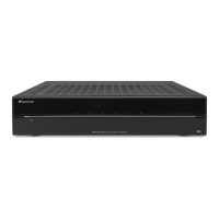
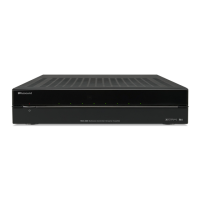
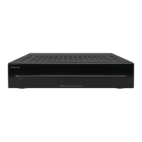
MCA-C3 Test Procedure
Page 31 of 77
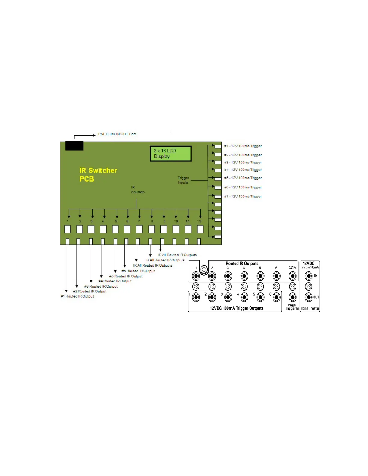
12. Connect the Source inputs of the IR Switcher PCB to the Routed IR ports of
the MCA-C3 using a cable with a 3.5mm mono plug on each end.
Source 1 IR Switcher to the Routed IR Output 1/7 of the MCA-C3
Source 2 IR Switcher to the Routed IR Output 2/8 of the MCA-C3
Source 3 IR Switcher to the Routed IR Output 3 of the MCA-C3
Source 4 IR Switcher to the Routed IR Output 4 of the MCA-C3
Source 5 IR Switcher to the Routed IR Output 5 of the MCA-C3
Source 6 IR Switcher to the Routed IR Output 6 of the MCA-C3
Source 7 IR Switcher to the Routed IR Output COM of the MCA-C3
13. Connect the Trigger Inputs of the IR Switcher PCB to the
12VDC 100ma Trigger Outputs to the MCA-C3 using a cable with a
3.5mm mono plug on each end.
Trigger 1 IR Switcher look at diagram in next step.
Trigger 2 IR Switcher look at diagram in next step.
Trigger 3 IR Switcher to the Trigger Output number 3 of the MCA-C3.
Trigger 4 IR Switcher to the Trigger Output number 4 of the MCA-C3.
Trigger 5 IR Switcher to the Trigger Output number 5 of the MCA-C3.
Trigger 6 IR Switcher to the Trigger Output number 6 of the MCA-C3.
Trigger 7 IR Switcher to the 12VDC Trigger OUT of the MCA-C3.
MCA-C3 Trigger Outputs
MCA-C3 Routed IR Output