119
Member of Exel group
DRT582165110
A - 2023/03
The flowmeter cables are connected to the 053X1 terminal block assembly.
For the flowmeter of component A (base):
• Wire 1 is connected to terminal block 1
• Wire 2 is connected to terminal block 7
• Wire 3 is connected to terminal block 4
For the flowmeter of component B (catalyst):
• Wire 1 is connected to terminal block 2
• Wire 2 is connected to terminal block 8
• Wire 3 is connected to terminal block 5
For the flowmeter of component C (diluent):
• Wire 1 is connected to terminal block 3
• Wire 2 is connected to terminal block 9
• Wire 3 is connected to terminal block 6
ATEX version
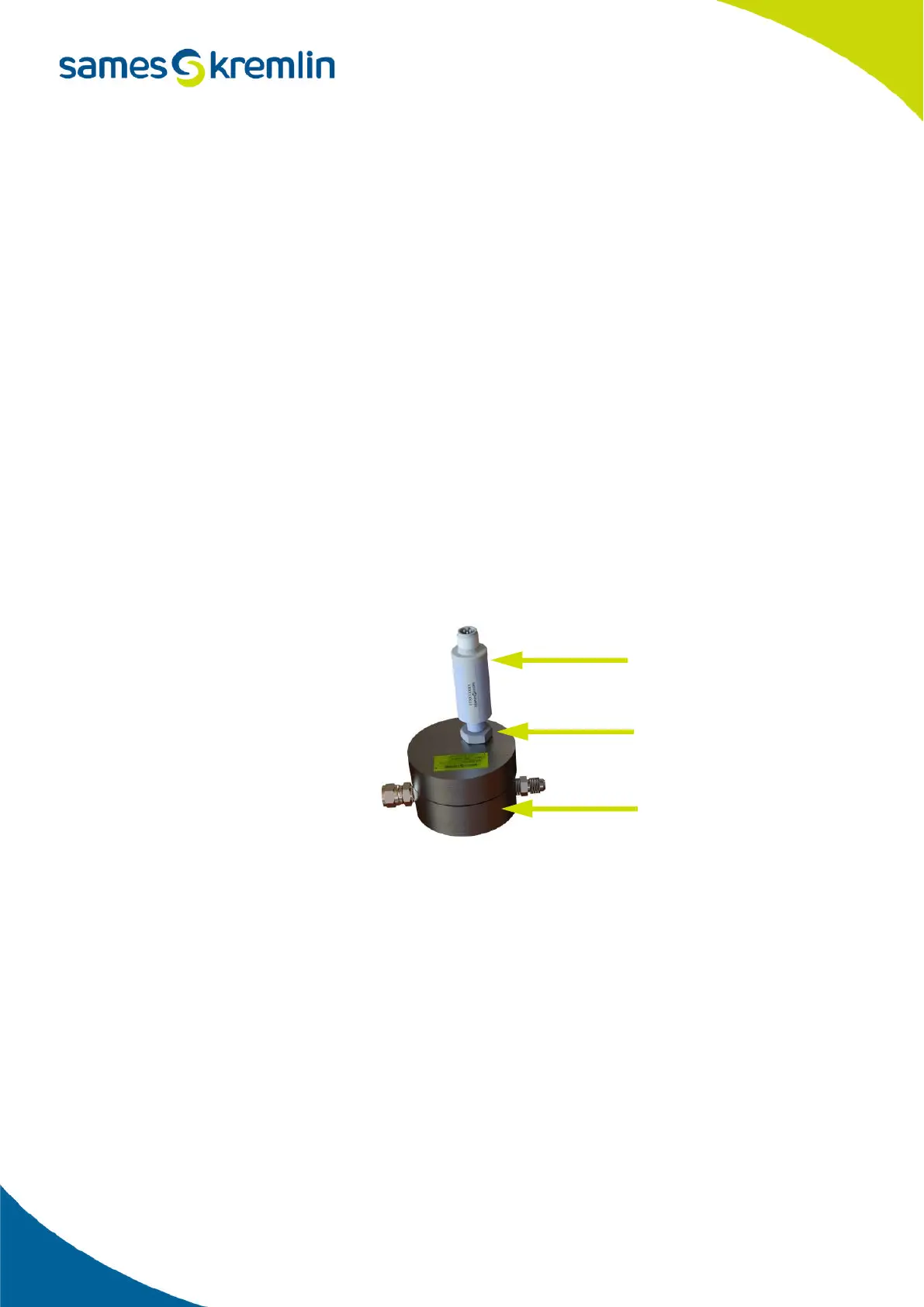
On the flowmeter side, the sensors are aimed and locked thanks to the locknut. The sensor must be screwed in order
to be in contact with the flowmeter and then it is necessary to lock the locknut in order to avoid that the sensor
unscrews in time.
The cables are marked to facilitate the connection of each flowmeter. The connector is screwed on the sensor on
one side and on the other side the cable is connected to the intrinsic barriers located inside the box.
Measuring sensor
Locknut
Flowmeter
 Loading...