Revised A 24 6301
3.3. Operating principle
3.3.1. Turbine rotation speed
The reading is obtained using a microphone. The air supply arrives at the clip holding the bellcup.
This clip is machined with a groove in which air passes with every rotation of the bellcup. This pres-
sure variation causes a noise or “frequency signal”, which is sent through the injector holder to a
microphone. The microphone in turn converts this frequency signal into electrical variations which are
sent to the speed regulation board.
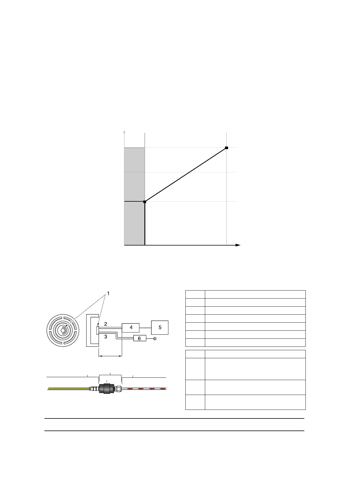
3.3.2. Microphone
1 Half moon groove
2 Microphone air return (Mic. OUT)
3 Microphone air supply (Mic. IN)
4 Microphone
5 Speed regulator board
6 Manual air regulator
7 1/4” Tube = (15 to 26 ft) or (4.5 to 8m)
8 Microphone air return1/4” tube
9 Microphone assembly (w/connector)
P/N: 851488 (6mm)
P/N: 459881(1/4”)
10 Microphone sleeve
PN: 546994
11 Microphone cable assembly
PN: 63-1080-00 (40m w/connector)
DES01241
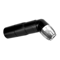
For extra hose length,
increase microphone IN pressure 0.6 psi/feet of tubing
OD
1/4” tube
26 feet / 8m
Maximum length
15 feet / 4.5m
Required minimum length
Microphone IN
Required pressure
25 - 45 PSI
DES01295
7
11
9
10
8
S01486
Mic Return air (Mic OUT)
To speed control board