Revised A 61 6301
6. Assembly and disassembly (continued)
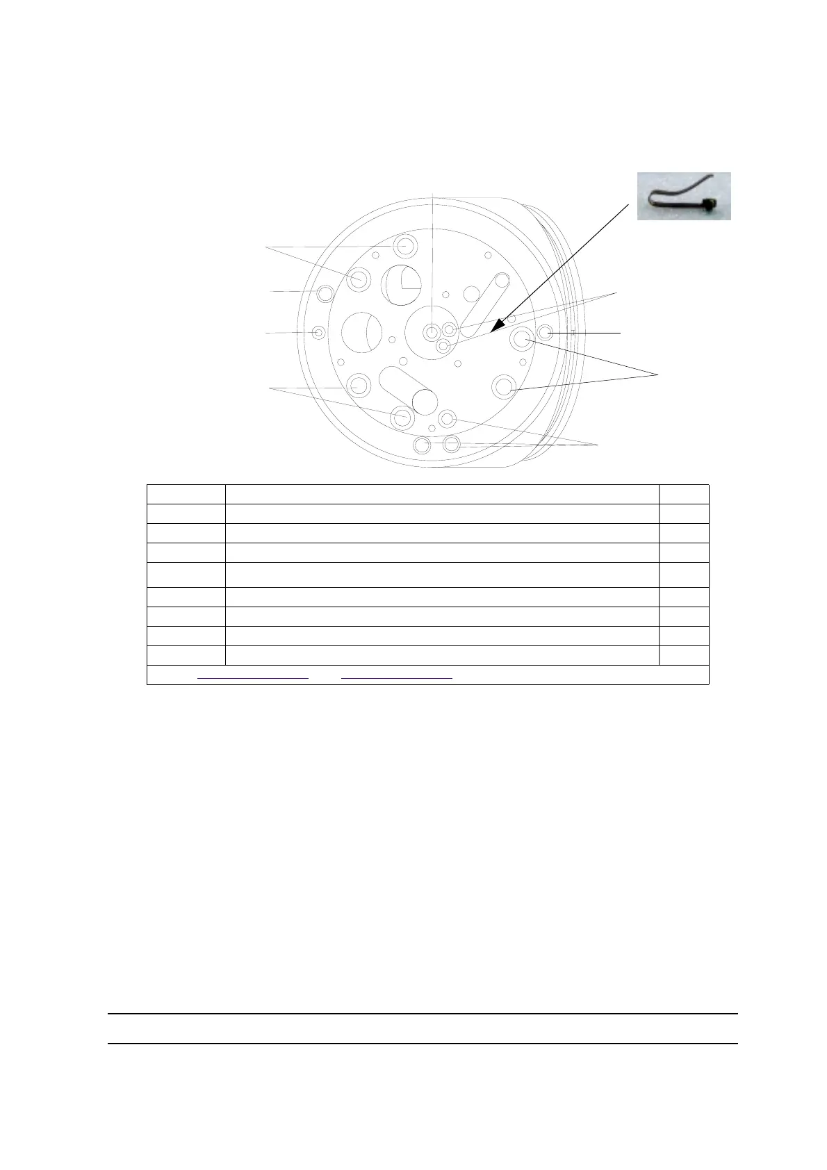
6.6. Robotic elbow
6.6.1. Disassembly
• Step 1: Remove all o-rings
• Step 2: Remove shaping air alignment pin.
• Step 3: Remove solvent injector and remove the two o-rings.
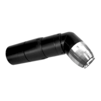
• Step 4: Remove high voltage contact.
6.6.2. Assembly
• Step 1: Install all o-rings.
• Step 2: Install shaping air alignment pin.
• Step 3: Apply a light film of dielectric grease on the solvent injector and install the two o-rings.
• Step 4: Install the high voltage contact and secure in place with one brass screw.
Item Description Qty
1 O-ring 2.75 x 1.6 - chemically inert (Microphone air) 2
2 O-ring 3.68 x 1.78 - chemically inert (Bearing and compensation air) 4
3 O-ring 6.07 x 1.78 - chemically inert (Turbine drive and brake air) 6
4 O-ring 2.9 x 1.2 - chemically inert for injector 2
4a Solvent injector 1
5 O-ring 3.1 x 1.6 - chemically inert for restrictor 2
6 Shaping air alignment pin 1
7 High voltage contact and screw 1
Note: see § 8.1 page 71
and see § 8.3 page 77 for Sames spare parts list
3
3
3
12
2
4 + 4a
5
6
DES01513
Item 7
High voltage contact also
used on the manifold