Revised A 28 6301
4. Diagrams (continued)
4.5. Microphone air
Microphone supply air is set by use of a remote regulator.
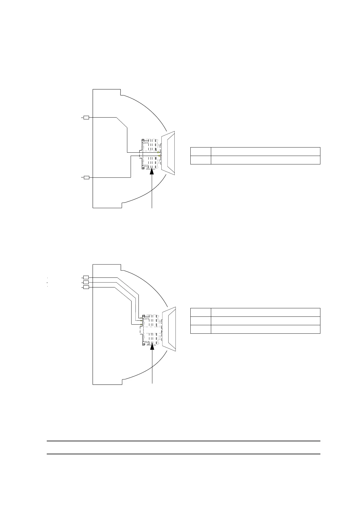
4.6. Turbine drive
Turbine drive air is controlled through a remote transducer.
23: The bearing air separates the rotor from the
stator.
22: Supplies air for turbine brake.
21: Supplies air for turbine drive.
The bellcup speed controller activates #21
through a remote transducer and #22 through
a solenoid.
26 Microphone IN
43 Microphone OUT
23 Bearing air
22 Turbine brake air
21 Turbine drive air
26
43
OD 1/4" NYLON
OD 1/4" NYLON
DES01019
Magnetic turbine
D:4/6 Nylon
D:4/6 Nylon
DES01020
23
22
21
OD 1/4" NYLON
OD 5/16" NYLON
OD 3/8" NYLON
Magnetic turbine
D:4/6 Nylon
D:6/8 Nylon
D:8/10 Nylon