Revised A 30 6301
4. Diagrams (continued)
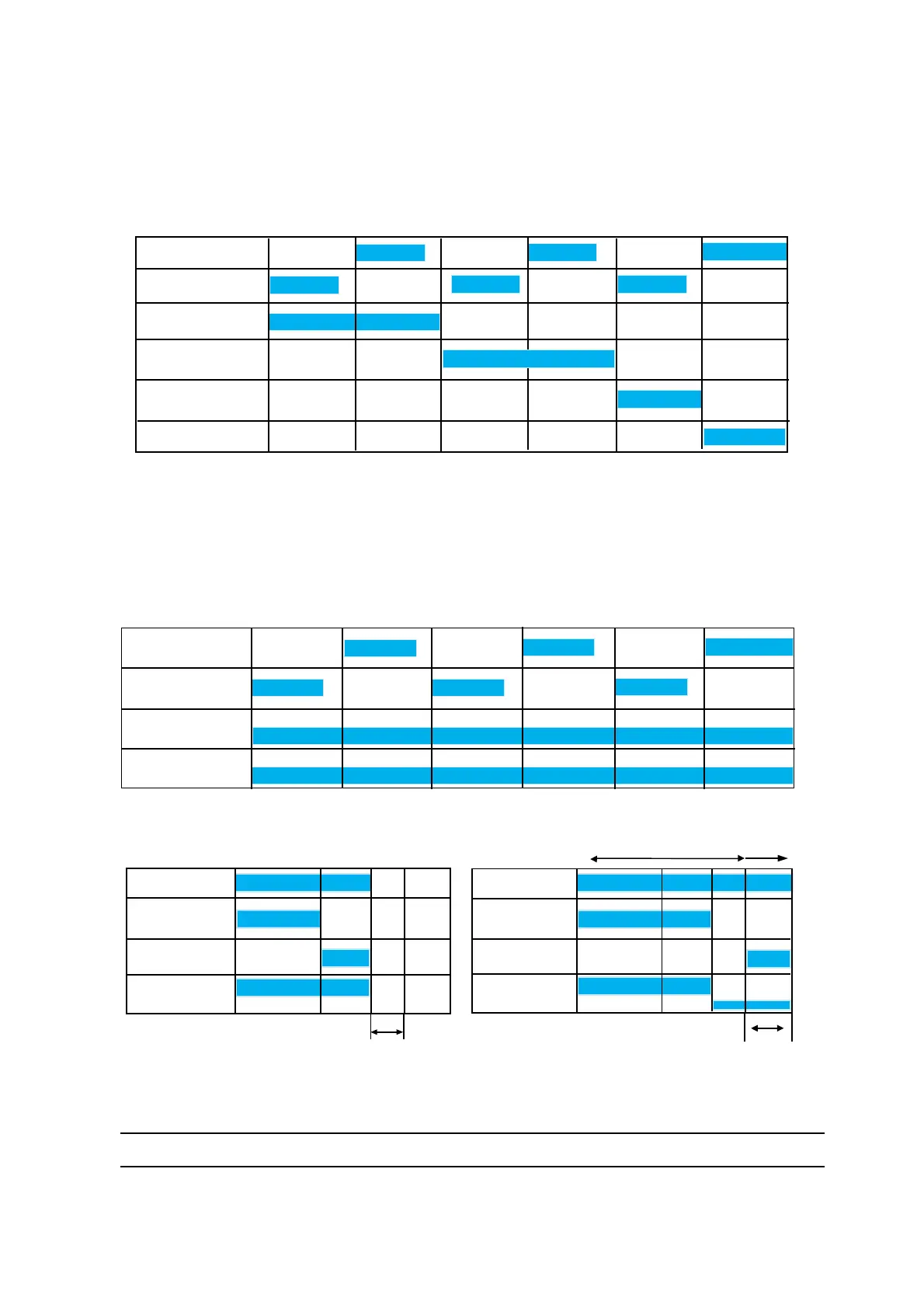
4.9. Color change and circuit flushing examples
• Standard conditions: 90 psi (6 bars) air, solvent and paint.
• Color change block and rinsing block distance to the atomizer (3 to 5 ft - 1 to 1.5 meter).
• Typical solvent consumption: 30cc
• Recommended injector solvent flow rate: 300 cc/min.
• Bellcup wash solvent flow rate: 250 cc/min.
• The use of restrictors is recommended if solvent flow rates are greater than specified above.
• The last air pulse is used to blow out and dry the exterior bell wash circuit in order to avoid solvent
spitting.
• Typical solvent consumption: 100 cc
0
12
3
4
5
6
DES01243
Main Air
Main Solvent
Bell wash solvent
Seconds
Color change cycle
Injector Wash
Solvent
Injector wash air
Bell wash air
0
1 2
3
4
5
6
DES01244
Main Air
Main Solvent
Paint regulator
Dump valve
High output (60psi (4 bar) pilot pressure
Seconds
Circuit flushing example
DES01245
0 1 2 2.5
D
1.6
0.5s
0
X
Y
Color valve
Dump valve
Trigger valve
Paint regulator
High output 90 psi
500cc/min. (max)
Low output
7.5 to 15 PSI
Low output
7.5 to 15 PSI
Color valve
Dump valve
Trigger valve
Paint regulator
Seconds
Optional
Filling cycle example
Typical
Seconds
Typical paint flow when trigger is on: 150 cc/min.
D = Delay to decrease the pilot air pressure of the paint regulator before opening the trigger.
X = Time for paint to flow from the color changer to bellcup
Y = Time of paint output from bellcup
NOTE: The optional fill cycle is normally used in situations where high voltage tracking through the dump line becomes an issue.