Revised A 58 6301
6. Assembly and disassembly (continued)
6.4 Turbine motor, injector, restrictor (continued)
6.4.2. Assembly
Injector and injector holder
• Step 1: Clean and inspect all components for damage, replace if necessary.
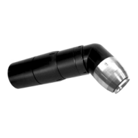
• Step 2: Insert the microphone o-rings into the manifold. Assemble the restrictor with the correct
size o-rings to the correct size restrictor (see § 8.9 page 83 for Sames spare parts lists), and push
into the manifold until completely inserted as illustrated.
• Step 3: Align the injector holder to the alignment pin on the manifold and secure with the 3 screws
using an 2.5 mm allen wrench.
• Step 4: Install the injector equipped with the o-rings.
• Step 5: Place the injector assembly into the injector holder and tighten by turning counterclock
wise (left hand thread) with the injector tool to a maximum torque of 12.3ft/lbs (7 N.m).
(see § 8.9 page 83 for Sames spare parts lists).
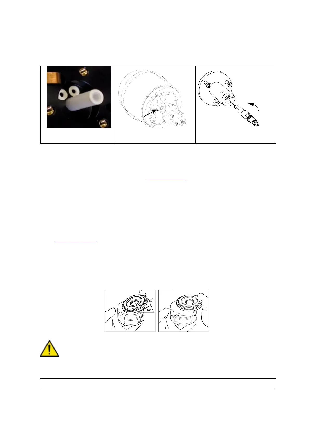
Turbine motor
• Step 1: Slide the rotor onto the stator as illustrated and avoid sudden impact which could cause
damage to the rotor.
WARNING : A sudden impact to the rotor will damage the turbine.
DES01511
DES01509
Step 2
Step 3 Step 4 and 5
DES00346
1/3
2/3
34