Revised A 55 6301
6. Assembly and disassembly (continued)
6.4. Turbine motor, injector, restrictor (continued)
6.4.1 Disassembly (continued)
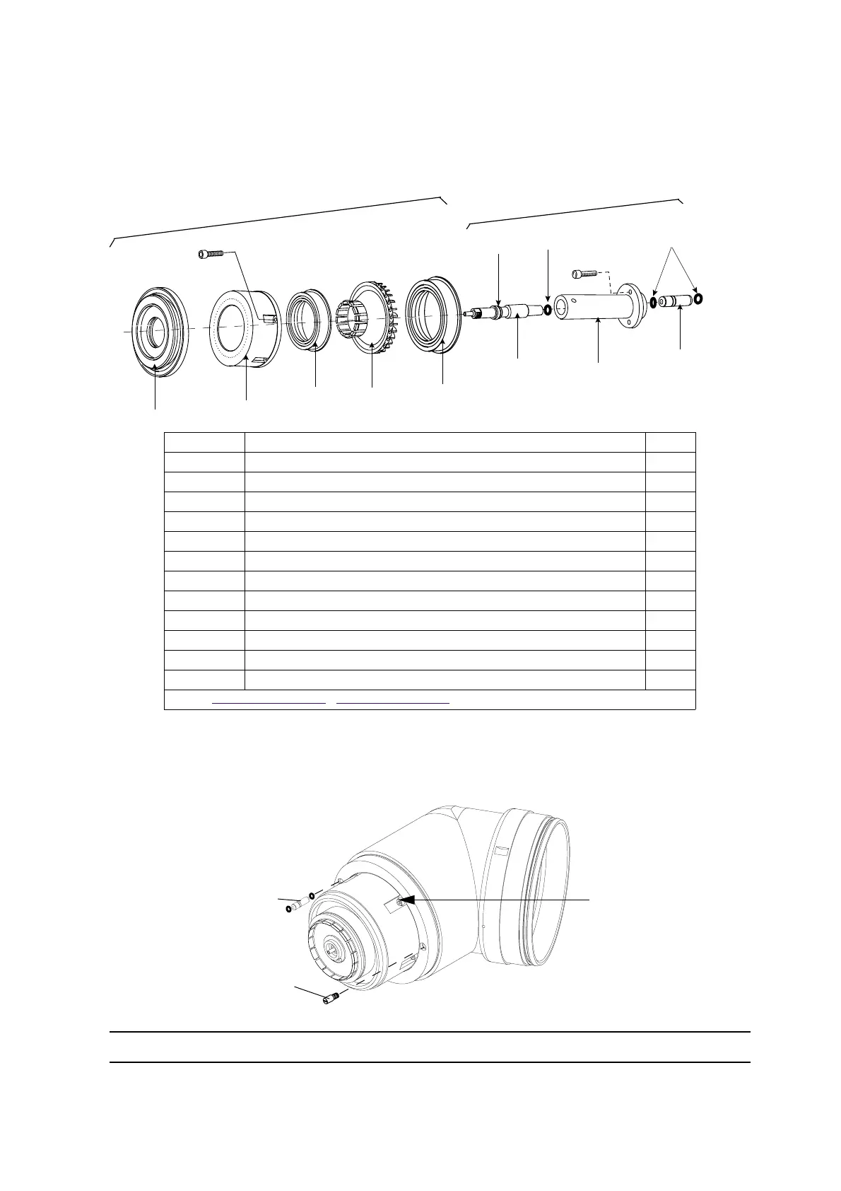
Turbine motor
• Step 1: Remove the 5 screws holding the turbine to the robotic elbow using a 2.5 mm allen wrench
then remove injector solvent and shaping air alignment pin.
Item Description Qty
1 Rotor 1
2 Screw M3 x 12 socket head s/s 8
3 Stator 1
4 Stator magnet 1
5 Drive wheel 1
6Deflector with o-ring size 52.07 x 2.62 viton 1
7 O-ring 5.28 x 1.78 chemically inert 1
8 Injector 1.8 mm 1
9 O-ring 2.0 x 1.25 chemically inert 2
10 Injector holder 1
11 O-ring 3.1 x 1.6 chemically inert 2
12 Restrictor 3.0 mm 1
Note: see § 8.1 page 71 , see § 8.8 page 82 for Sames spare parts lists
Injector + holder
Turbine motor
1
2
3
4
5
6
7
8
9
10
11
2
12
DES01504
DES01505
Solvent injector
Shaping air ring alignment
pin
Turbine mounting screw