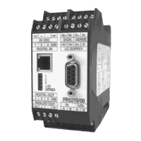
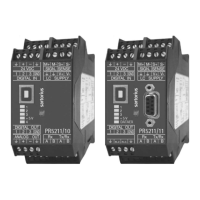
ProfiBus Interface PR 5211 Instrument Manual
EN-62 Sartorius
6.1.6.2 Parameter Reading
The following is done subsequently:
Master Transmitter
Write parameter index in register 21
(method see chapter 6.1.5.2)
The value is stored intermediately
Set Bit 124, get parameter
(method see chapter 6.1.5.3)
The parameter is copied to register 20.
The bit is reset immediately
Read parameter value in register 20
(method see chapter 6.1.5.1)
6.1.6.3 Calibration Procedure
The calibration is controlled by writing parameters subsequently:
Master Transmitter
Set parameter P20 to 1 (start Cal)
(method see chapter 6.1.6.1)
The CAL switch is tested, the calibration procedure is
started. If the CAL switch is 'locked', an error code is
stored in LastError, see chapter 6.2.5.
Proceed with calibration
(parameter see chapter 6.3.2)
(method see chapter 6.1.6.1)
CmdBusy and CmdError as in chapter 6.1.5.6
If a parameter is not within the valid value range,
an error code is stored in LastError. The cause can be
detedted by reading register 4, byte 3.
Set parameter P20 to 3 (SaveAndExit)
(method see chapter 6.1.6.1)
Data are stored in the non-volatile EAROM
Set parameter P20 to 4 (UndoAndQuitCal)
(method see chapter 6.1.6.1)
All modified data are erased, continue with the
previously stored data.
6.1.6.4 Reset transmitter to default (factory data)
Master Transmitter
Set parameter P20 to 1 (Start Cal)
(method see chapter 6.1.6.1)
The CAL switch is tested, if the switch is not in the
'locked' position, the procedure is started.
Set parameter P20 to 2 (default = factory data)
(method see chapter 6.1.6.1)
Default data are taken as calibration data.
All ADU data will be reset, see chapter 4.9.
Set parameter P20 to 3 (SaveAndExit)
(method see chapter 6.1.6.1)
Data are stored in the non-volatile EAROM.
 Loading...