PR 5211 Instrument Manual Installing the Instrument
Sartorius EN-19
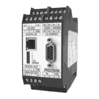
3.2.6 Load Cell Connection
The cable colours shown in this chapter are of Sartorius load cells series PR 62XX.
Before connection of other types, strictly necessary read the instructions concerning
cable colours of the load cell/platform.
• The distance between the measuring cables and the power cables should be at least 1 m.
• The measuring cables should be laid in separate cable conduits or steel pipes connected to earth potential.
• Power cables should be crossed at right angles.
Load cell supply circuit
The voltage for load cell supply is firmly adjusted to 12 V DC and
protected by multifuse elements (see chapter
1.4.6).
Load resistance of load cells ≥75 ¥, e.g. 8 load cells of 650 ¥ each.
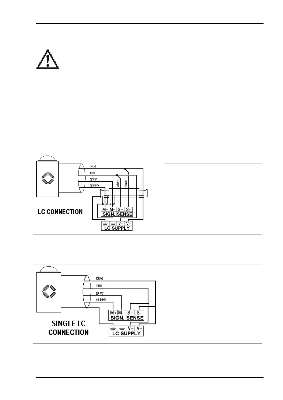
3.2.6.1 Connection of one Load Cell in 6-Wire Technique
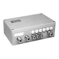
See label on the housing (see chapter 2.3) and documentation for the junction box.
Terminal Description
SIGN. M+
SIGN. M-
SENSE S+
SENSE S-
LC SUPPLY V+
LC SUPPLY V-
+ signal / + LC output
- signal / - LC output
+ sense
- sense
+ supply / + excitation
- supply / - excitation
3.2.6.2 Connection of one Load Cell in 4-Wire Technique
Pay attention, that SENSE S+ has to be connected to LC SUPPLY V+ and SENSE S- has to be connected to
LC SUPPLY V- directly at the transmitter.
Terminal Description
SIGN. M+
SIGN. M-
SENSE S+
SENSE S-
LC SUPPLY V+
LC SUPPLY V-
+ signal / + LC output
- signal / - LC output
+ sense
- sense
+ supply / + excitation
- supply / - excitation
3.2.6.3 Connection of PR 6221 Load Cells
Please refer to the installation manual PR 6021/08…68.
 Loading...