IPE100 indicator NU-IPE100-IO-USER-E-0212
8
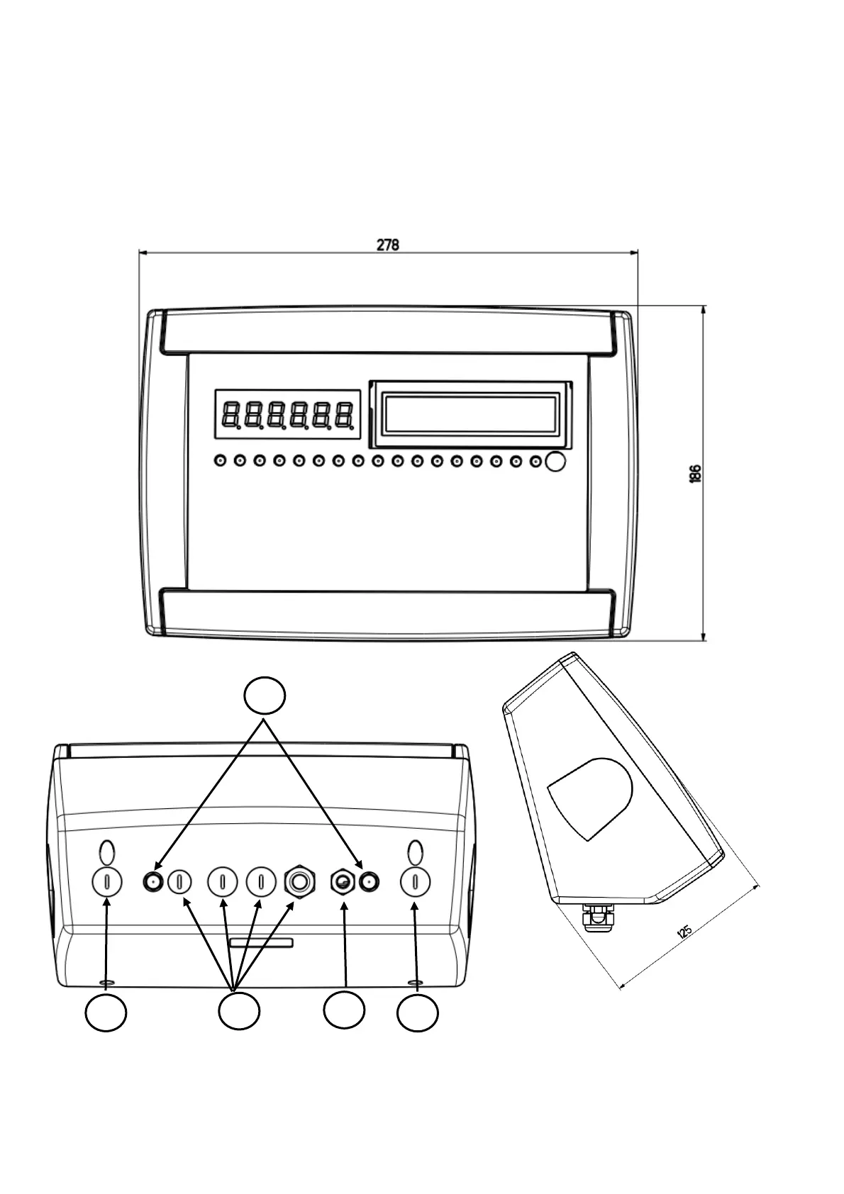
Figure 2 – Measurements and dimensions in mm
1) RJ45 connector
2) Fixing for shelf or column mounting
3/5) Available for load cells / serial lines / inputs / outputs.
4) Power supply input.
3. INSTALLATION
3.1 IPE100 CASE AND DIMENSIONS
ABS MODEL
The indicator has an IP65 ABS case, whose external dimensions are shown in the Figure. It can be simply put on a table or
fixed to a shelf or column available on request.
NOTE: If the identification plate is supplied separately (therefore not attached to the indicator), it is advisable to
attach it to the indicator, in order to be able to identify the instrument.
1
2
3
4
5