CABLING THE PDU: ETHERNET, DATABUS AND SENSORS
How to connect the PDU to LAN?
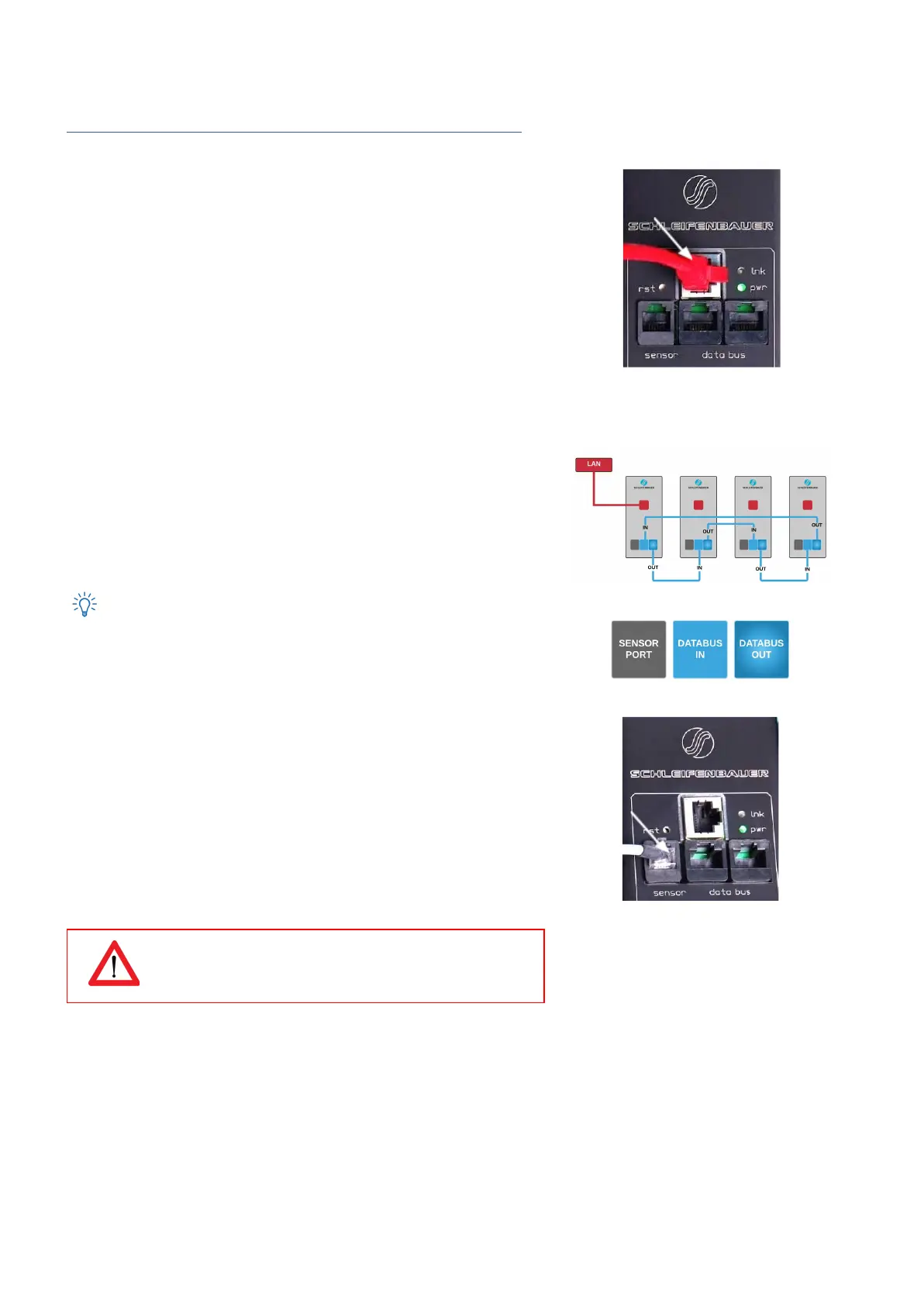
10/100 Mbps LAN Ethernet port
Connecting the PDU to a Local Area Network (LAN) provides
communication through an Ethernet network, if the PDU is connected
exclusively, or simultaneously with the databus.
The RJ45 connector for the network cable must be plugged into the
Ethernet port:
● Connect the RJ45 Ethernet cable to the Ethernet port on the PDU
and to the Ethernet connector on the LAN device; when
connected, the orange LED – marked “lnk” - will blink
How to connect a databus?
There are three black communication ports. One is marked as sensorport,
the other two as databus ports (in and out).
The left databus port is the “incoming” databus port. The right databus
port is “outgoing”. This is a MUST HAVE for devices in bridge mode. For
devices in hybrid mode it is a NICE TO HAVE.
The serial databus in the Schleifenbauer PDU uses CAT5 patch cables.
The terms IN and OUT are arguable. Data will be send and received
by both ports but to close the databus ring, it is recommended to follow
the connection diagram. See it as the best way to daisy chain PDUs.
How to connect sensors to a PDU?
The PDU has a RJ12 connector sensor port for connecting a digital
temperature sensor, a combined sensor for temperature/humidity or one
or multiple dry switch contacts.
Plug and play
The PDU registers which sensor is connected and automatically adapts
the menu in the display to the sensor(s) that it has detected.
Use Schleifenbauer sensors only
V252_User manual
Schleifenbauer PDU