Field in which the maximum current [A] that the actual current is allowed to reach is configured
for this outlet. Crossing this limit will lead to an alert
➢ See also chapter: System tab > Reset & Settings
This functionality makes it possible to switch outlets in a row during startup (if configured). So,
one-by-one and not all at once. You can configure the time of switching in seconds.
Configurable downtime when an outlet is power cycled. Which means that after the command to
power cycle (shut outlet off and start again) is given, the outlet will be switched on again after the
configured downtime has passed.
➢ See “Unlock” at the end of this table
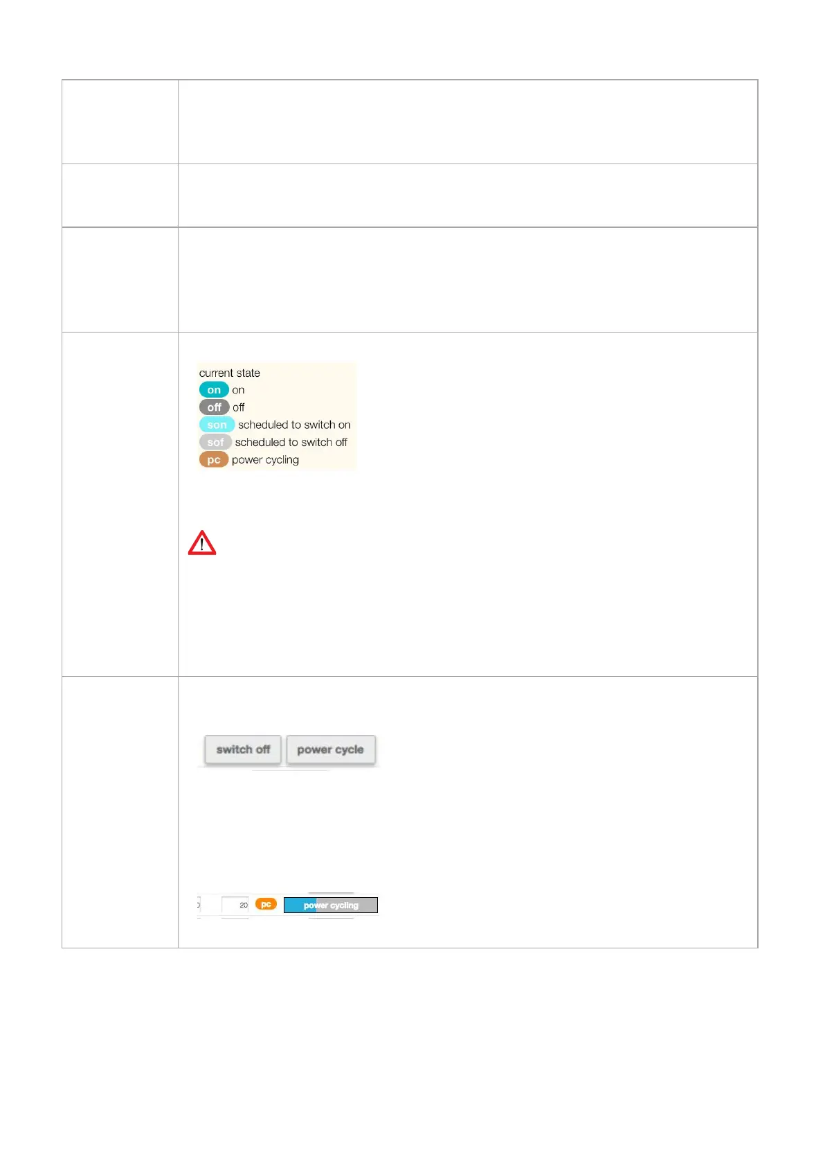
Shows the configured OR actual outlet state. There are several possibilities:
➢
See “Unlock” at the end of this table
Devices built up to and including January 2018: the displayed outlet state is the user configured state.
For devices built from February 2018 on: the displayed outlet state is the ACTUAL state because of the
implementation of new hardware which measures the actual state of the outlet. Depending the “power
up/down outlet behaviour” you can see changes in the overview.
After the “unlock” sign is clicked, a confirmation is needed to change the state of the outlet.
There are 2 possibilities:
● Switch off
● Power cycle (
See “power cycle time” in this table)
After you have made a choice, the state of the outlet is changing (
See “state” in this table)
While the given command is running, a status bar shows the progression of the action.
V252_User manual
Schleifenbauer PDU