© 2014 SeaStar Solutions Optimus Installation Manual, Rev. E
6-10
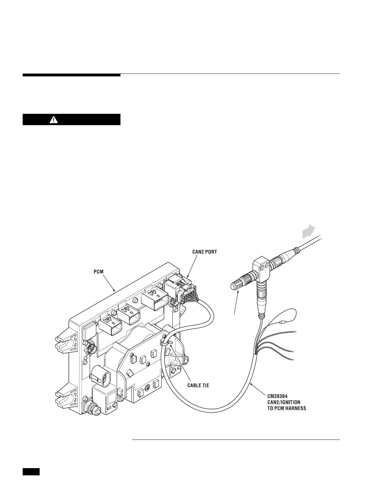
6.4 Ignition Sensing
GREY/BLACK
ANALOG
TACHOMETER
RED (X 1)
NOT USED
MALE
TERMINATOR
VIOLET (X2)
IGNITION
CAN2
NETWORK
The CM20304 harness connects through the CAN2 port on the PCM.
It has two violet ignition sensing wires that must be connected
to an
ignition source (has 12V when ignition is on). See section 6.4.1 for
important ignition splicing instructions.
Twin-engine applications: Connect one sensing wire to the starboard
ignition and the other to the port ignition.
Triple- and quad-engine applications: The ignition sensing wires must
be connected in such a way that an ignition-on signal is received when
any of the engine ignition switches are on. Some vessels may already
be wired to deliver such an ignition signal, but you may require one or
two Dual Ignition Kits (HA1201) to appropriately combine the ignition
sources into a pair of signals for connection to the sensing wires.
Single engine applications: Connect one sensing wire to the engine
ignition. Connect the second sensing wire to either a separately
switched 12V source (preferred) or the same source. NEVER leave
the second sensing wire unconnected. These connection options
are illustrated in figure 2-3.
Figure 6-11.
THE INTEGRITY OF THE IGNITION
SENSING CIRCUIT IS CRITICAL
TO THE SAFE OPERATION OF
THE STEERING SYSTEM. ALWAYS
CONNECT BOTH SENSING LEADS
AND ENSURE THAT WIRING AND
SPLICES ARE PROPERLY STRAIN-
RELIEVED AND PROTECTED
FROM DAMAGE, WATER, OR
OTHER HAZARDS.
DANGER