© 2014 SeaStar Solutions Optimus Installation Manual, Rev. E
6-14
6.7 Buzzer Kit (Optional)
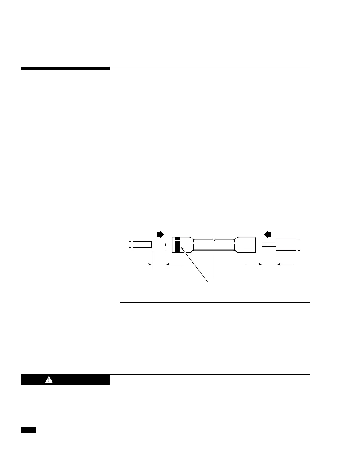
Figure 6-16.
7.6 mm (0.3")
NOTE
MARKER
7.6 mm (0.3")
BUZZER & HARNESS
18 AWG
EXTENSION WIRE
16 AWG
Crimp connections as follows:
•Stripthewires7.6mm(.3”)fromtheendandinsertintothebarrel
of the butt splices provided (Molex 0191640043) observing the
correct orientation shown below:
Dual station boats do not require a CANtrak display at the second
station. However, you must install a buzzer kit to notify the operator
that the steering system has a fault and needs attention.
Locate the buzzer under the second station dash, near the helm. A
warning label is included in the buzzer kit and MUST be applied to
the dash in a visible location near the helm.
Connect the positive (yellow) and negative (pink) leads of the buzzer to the
positive (yellow) and negative (pink) flying leads on the CANtrak harness at
the main station.
Secure the wires adjacent to the splice for strain relief.
•
Making sure the wire end is properly seated, make the crimp connection
using the recommended tool (Molex 0640014500, not included).
•Applyheatdirectlytothesplice,workingfromthecenteroutto
the edges, using a hot air gun or other heat source, until the tubing
shrinks and the adhesive flows.
•Allowtocoolbeforeinspectingspliceandcheckingtheintegrity.
Reversing the polarity of the buzzer may result in damage to the
CANtrak harness and/or CANtrak display. 16AWG wire has been
included in the kit to power the buzzer and comply with ABYC
E-11. Refer to the ABYC E-11 for required gauge if longer wire
runs are required.
CAUTION