© 2014 SeaStar Solutions Optimus Installation Manual, Rev. E
5-12
1.
Using an approved quality marine grease (such as Johnson/Evinrude
triple guard, Quicksilver anti-corrosion, Yamaha marine grease or
equivalent), liberally lubricate the tilt tube and support rod (Item
9) and slide the support rod through the engine tilt tube.
2.
Lightly grease the tiller bolt (Item 2) & partially screw into appropriate
hole in the tiller arm to assure a proper fit. Then remove the tiller
bolt and go to Step 3.
3. Select appropriate insert diagram from page 5-14 through page
5-17 to determine proper orientation of the SmartCylinder assembly,
the tiller bolt and self locking nut (Items 13, 2 and 1). Grease
tiller bolt as indicated and fully thread tiller bolt (Item 2) into the
steering arm. While holding the head of the tiller bolt with a
wrench, tighten the tiller nut (Item 1) to the specified torque.
WARNING
5.4 SmartCylinder Mounting
Sensor harness MUST be properly secured to hoses (see Section 5.7).
If your engine application is such that interference will occur if the
SmartCylinder is moved throughout its full stroke, leave the
SmartCylinder support brackets off for purge and calibration.
Before beginning installation make sure that all mounting hardware is
available and the tiller arm and the tilt tube bolt holes are clean and
free from rust or burrs.
Assembly drawings for specific engine applications can be found on
page 5-14 through page 5-17 of this manual.
IF THE ENGINE MANUFACTURER HAS INSTALLED CAPS, PLUGS
AND/OR SCREWS INTO THE TILLER ARM, THESE CAPS, PLUGS
AND/OR SCREWS MUST BE REMOVED PRIOR TO CONTINUING
ON WITH INSTALLATION.
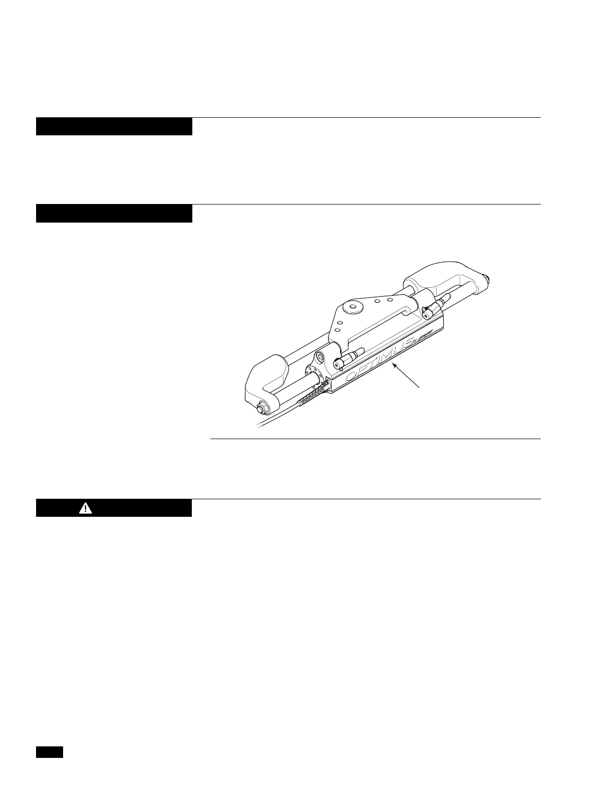
Figure 5-14.
NOTICE
NOTICE
DO NOT REMOVE OR FLIP SENSOR