© 2014 SeaStar Solutions Optimus Installation Manual, Rev. E
4-3
4.3 Plan Your Component Placement
The helm is an electronic unit and send signals to the Pump Control
Module (PCM) via an electrical harness supplied with the system.
There is no steering fluid in the helm.
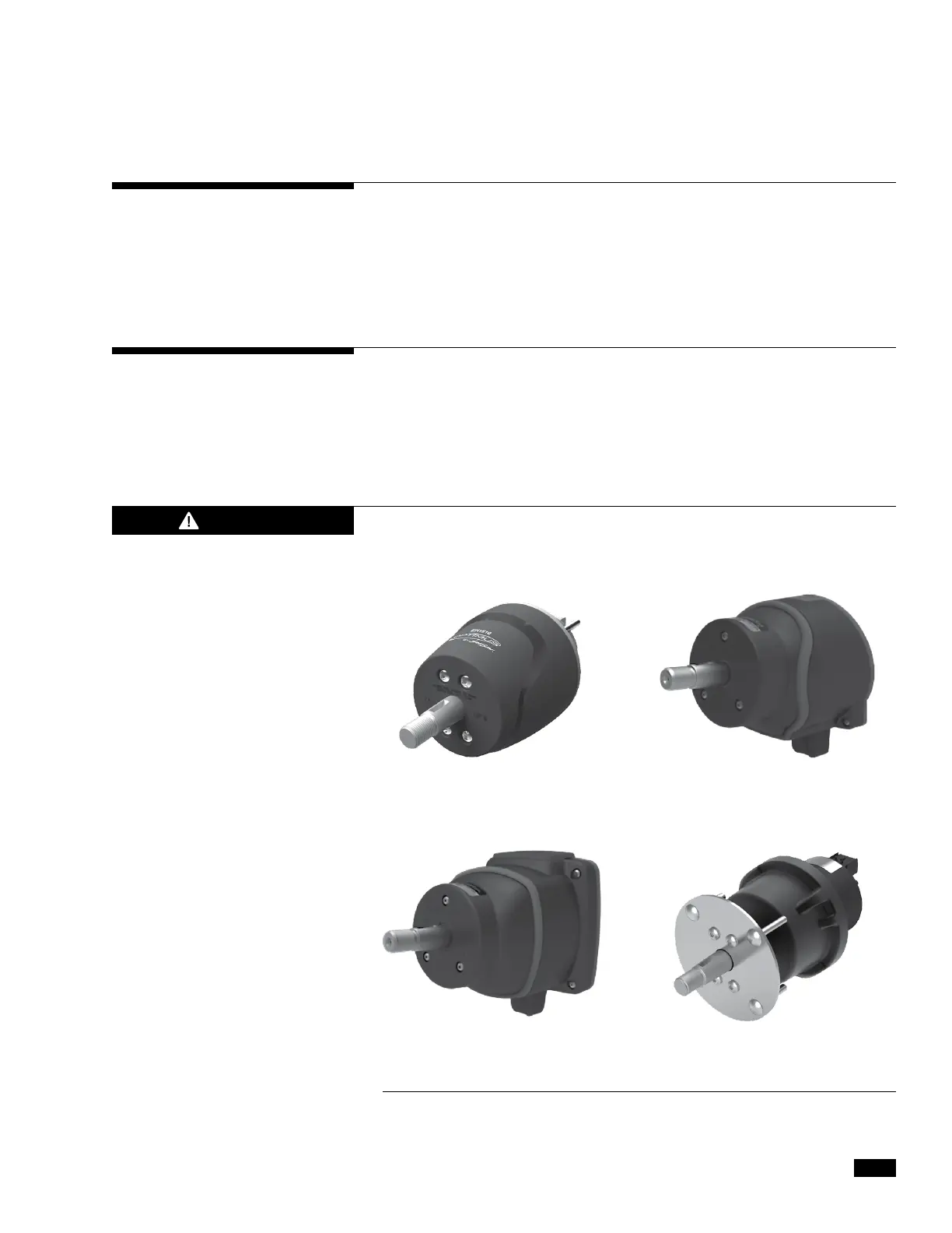
There are four helm styles available for the Optimus EPS system.
One is required for each helm station. On multiple helm station
boats, different style helms may be used at different stations.
EPS Front Mount Helm
Part No. EH1510
EPS Classic Tilt Helm
Part No. EH1550
EPS Sport Plus Tilt Helm
Part No. EH1530
EPS Rear Mount Helm
Part No. EH1570
Review the detailed information for each of the following components
and determine where they will be located on the boat. Pay particular
attention to the harness length information, as this may impact the
choice of component locations. During this process, confirm that the
correct harness lengths are available.
4.3.1 Electronic Helm(s)
The helm may effect a ship’s or the autopilot’s compass. For less
than one degree of effect keep the EPS helm and the compass a
minimum of 24 inches (61 cm) apart.
For mounting templates, please see Appendix A.
Figure 4-2.
CAUTION