© by SEMIKRON / 2017-09-07 / Technical Explanation / SKiiP
4
Page 18/73
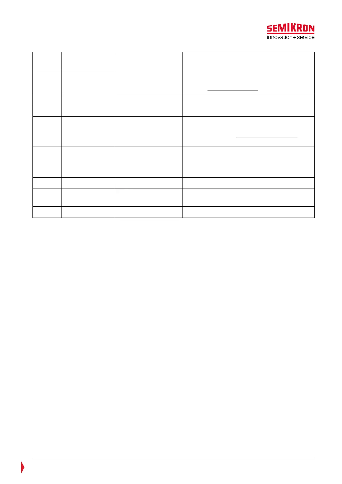
17 CMN_GND
Ground for CMN_HALT,
CMN_GPIO1/2
Internally connected to PWR_GND
18 CMN_GPIO1
Digital Input/Output
General purpose IO
Inverted CMN_HALT signal (except in case of
an activated FRT-function, please refer to
chapter CMN_GPIO1 signal, p. 26
19 CMN_TEMP_GND Ground for CMN_TEMP
20 CMN_DCL_GND Ground for CMN_DCL
21 HB_BOT
Switching signal input
for low side IGBT
LOW = Low side IGBT off
HIGH = Low side IGBT on
For details refer to Switching Signal Inputs,
p.21
22 HB_GND
Ground for
CMN_HB_TOP,
CMN_HB_BOT,
CMN_HB_RSRVD
Internally connected to PWR_GND
23 HB_I_GND Ground for HB_I
24 CAN_L
CAN interface INPUT/
OUTPUT LOW
Input impedance = very high;
Specification according to ISO 11898.
25 CAN_L Internally connected to pin 24