2.3. ASTERX-U DESIGN
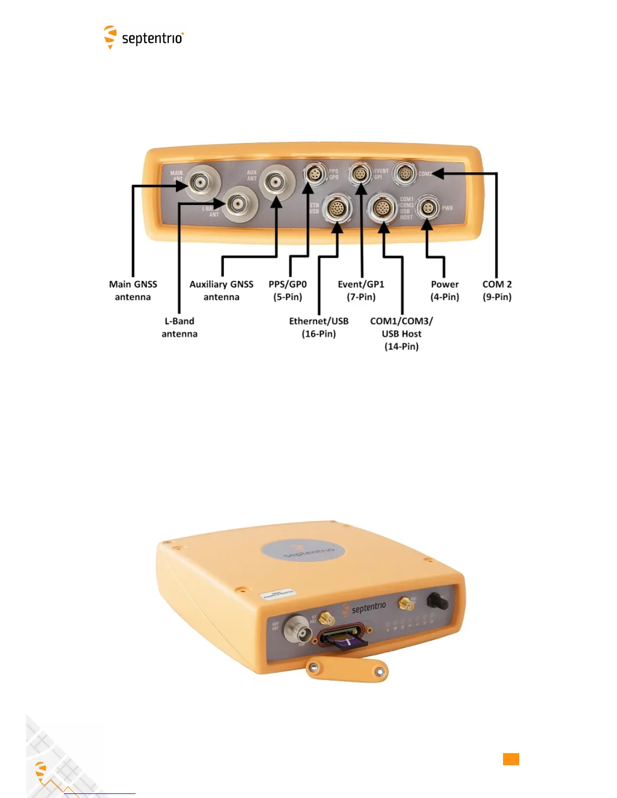
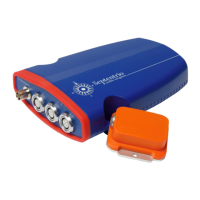
2.3.3 Rear panel
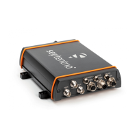
Figure 2-2 shows the layout of the rear-panel connectors on the AsteRx-U. The PIN
assigments for each socket can be found in the Appendix.
Figure 2-2: AsteRx-U rear-panel layout
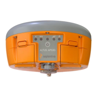
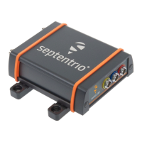
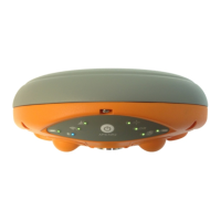
2.3.4 SIM card slot
The SIM card can be inserted into the slot in the front panel of the AsteRx-U as shown in
Figure 2-3.
Important: Only insert or remove the SIM card while the unit is powered down.
Figure 2-3: SIM card slot on AsteRx-U
12