Installation and Setup DF-310E 13
4 Installation and Setup
This procedure describes installation of the analyzer without options and with
the voltage output set to 0-10 VDC. Options may affect the setup procedure
described in this section. If your analyzer is equipped with options, refer to
the appropriate section to determine changes to the setup.
NOTE
The screens shown in this manual have values that may not match
the actual values displayed during your setup.
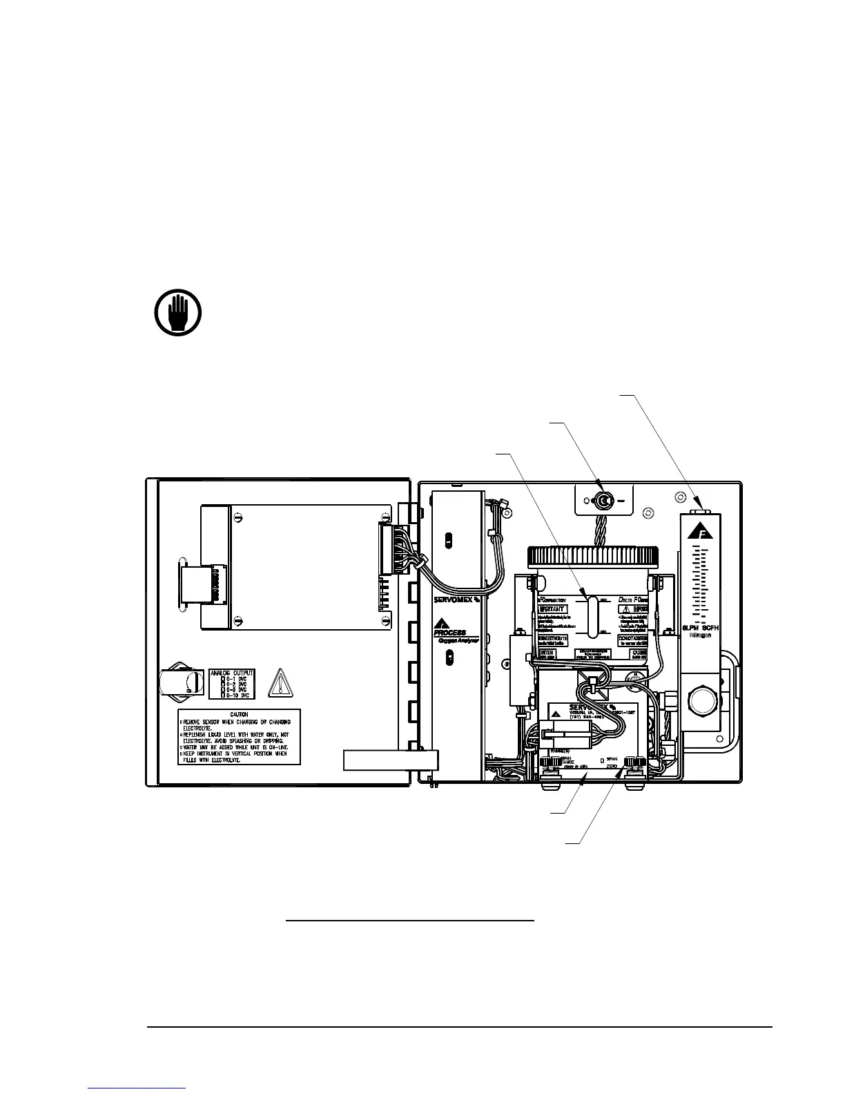
SENSOR MOUNTING
THUMB SCREWS
OXYGEN SENSOR
ROTOMETER
VALVE (optional)
POWER SWITCH
ELECTROLYTE RESERVOIR
WITH MIN-MAX LINES
Figure 2: Major Internal Components