Connecting to External Devices DF-310E 45
J2-1 A3-COM Alarm 3 Common
J2-2 A3-NO Alarm 3 Normally Open
J2-3 A3-NC Alarm 3 Normally Closed
J2-4 UNUSED
J2-5 A4-COM Alarm 4 Common
J2-6 A4-NO Alarm 4 Normally Open
J2-7 A4-NC Alarm 4 Normally Closed
J2-8 GND Ground
Table 5: Relay Port Connectors (J1, J2) Pin Out
7.3 Analog Outputs
In addition to the wiring of the analog outputs as described below, see page 70 for additional
information on scaling the outputs through the firmware.
7.3.1 Analog Voltage Output
Connector J4 provides connections to the non-isolated analog voltage output signal (0 to 5, or 0
to 10 VDC, selectable). For details regarding how to switch the full-scale output see section
7.3.1.1 below.
FLOW-B
UNUSED
FLOW-A
UNUSED
PUMP +
PUMP -
A OUT -
A OUT +
GND
UNUSED
UNUSED
UNUSED
UNUSED
24V RTN
UNUSED
+24V
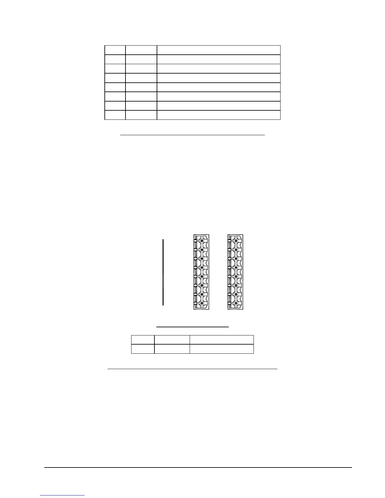
J3 J4
J3/J4 Connector Wiring
J4-1 AOUT+ Analog Voltage Output +
J4-2 AOUT- Analog Voltage Output -
Table 6: Analog Voltage Output Connector (J4) Pin Out
7.3.1.1 Procedure to change the Full Scale Analog Output Voltage
The following procedure should be used to change the full scale analog output voltage. The
options are 5.0 and 10.0 VDC.
1. Shut-off and disconnect all power from the analyzer.
2. Label and remove all connections from the rear of the analyzer.
3. Open the door and disconnect the sensor and display cables. See page 13.
4. Remove the two screws from the rear of the unit. See page 18.