Connecting to External Devices DF-310E 47
7.3.3 Alignment Procedure for Analog Voltage and Current Loop
Outputs
All output connections should be made before the alignment is started. It is assumed for the
purpose of this alignment that the full-scale analog voltage output is 10 VDC.
Use the Test Outputs screen as described on page 89 to set the output to the desired level after
which the alignment adjustments are made as follows:
1. Set the output to 0%
2. Adjust the analog voltage output (1) to 0.000 V +/- 1mV, adjust the current loop output
(2) to 4.00mA +/- .01mA
3. Set the output to 100%
4. Adjust the analog voltage output (3) to 10.000 V +/- 1 mV, and adjust the current loop
output (4) to 20.00mA +/- .01mA.
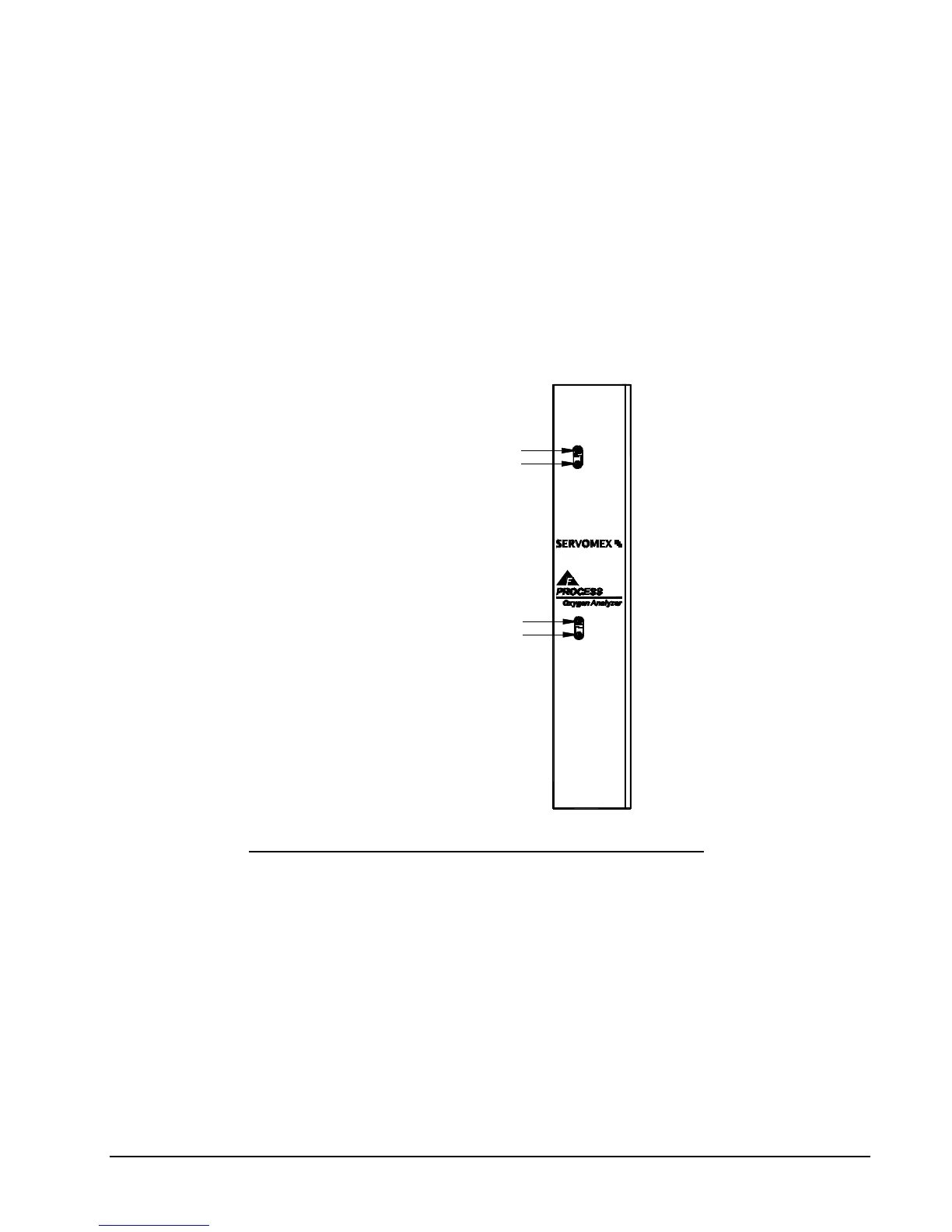
0-10 VDC: SPAN ADJUSTMENT (3)
0-10 VDC: 0 VDC ADJUSTMENT (1)
4-20 mA: 4 mA ADJUSTMENT (2)
4-20 mA: 20 mA ADJUSTMENT (4)
Figure 21: Analog Voltage Output and 4-20mA Adjustments
7.4 Remote Controls
7.4.1 Remote Sensor Control – J6 Connector
If equipped, the oxygen sensor can be turned on and off remotely through the pins labeled EXT 1
or EXT 2 on the J6 connector. If equipped, the EXT Functions screen, see page 91, will indicate
to what set of EXT contacts this option is assigned, either 1 or 2.