Connecting to External Devices DF-310E 43
7 Connecting to External Devices
The analyzer can be interfaced to a variety of external devices via the ports on the rear panel.
Alarm contacts, voltage, and current outputs, and serial communications are supported.
NOTE
When using external devices to monitor the O2 reading, the analyzer
should never be left in a menu screen unattended, but always in the O2
readout mode.
7.1 The Comm Port
The optional Comm Port is used for communication via RS-232C or RS-485 protocol. Up to 32
units may be accessed via RS-485. Operating parameters are 8 bits, no parity, and one stop bit.
Baud rate may be selected from the menu on the display.
A library of interface functions, written in C, is available to allow programmers to create custom
interface program for accessing the communication port. The Interface C Library Reference
Manual comes with a disk containing Microsoft and Borland versions of the object code.
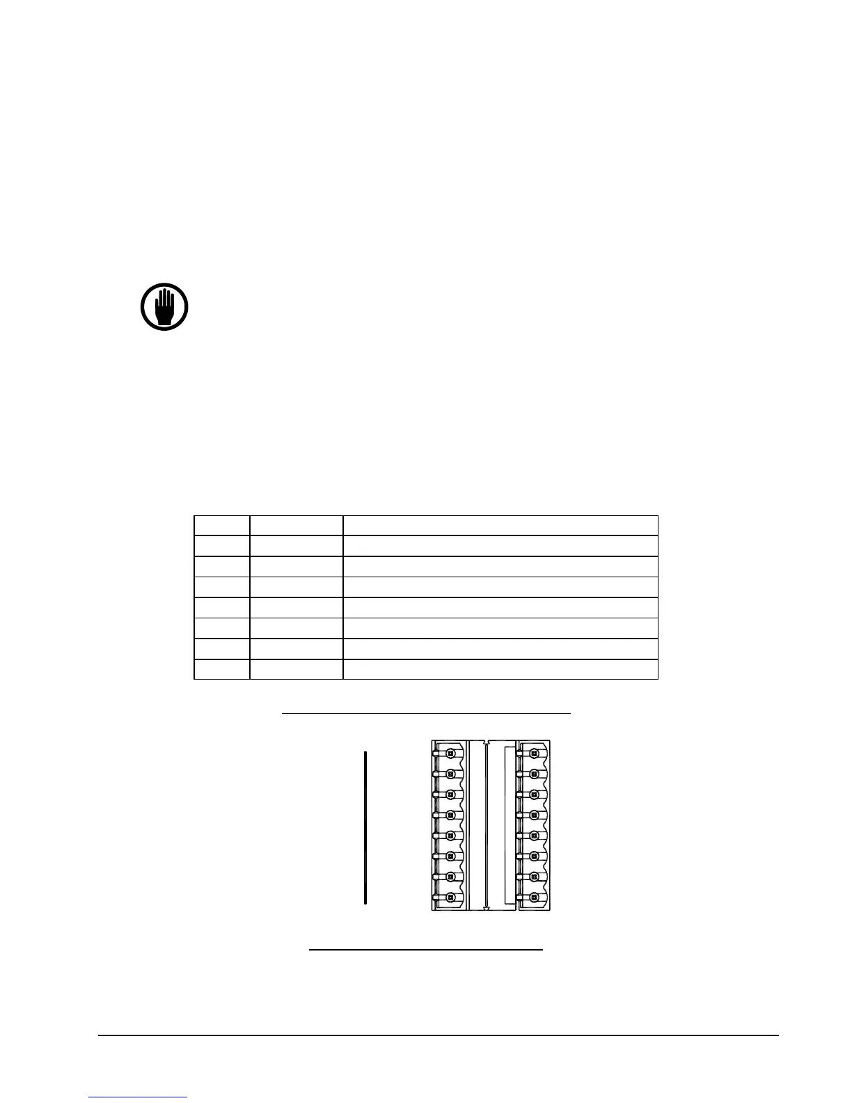
The Comm port (J8) terminals are defined as follows:
J8-1 485-RX + Data received by the analyzer from the device (RS-485)
J8-2 485-TX + Data transmitted by the analyzer to the device (RS-485)
J8-3 232-TX Data transmitted by the analyzer to the device (RS-232)
J8-4 232-RX Data received by the analyzer from the device (RS-232)
J8-5 485-RX - Data received by the analyzer from the device (RS-485)
J8-6 UNUSED
J8-7 485-TX - Data transmitted by the analyzer to the device (RS-485)
J8-8 232-GND Ground
Table 4: Comm Port (J8) Connector Pinout
232-GND
485-TX -
UNUSED
485-RX -
232-RX
232-TX
485-TX +
485-RX +
GND (H-)
SE -
SE+ (H+)
SNSR -
SNSR +
UNUSED
TEMP -
TEMP +
Figure 18: J7/J8 Connector Wiring