54 DF-310E Connecting to External Devices
2) Open the R4 door or remove the R7 cover. Attach the temperature measuring probe to the
side of the oxygen sensor. Be sure to cover the enclosure opening to prevent cooling.
3) Turn on the analyzer and enclosure heater. Allow at least four hours for the enclosure
temperature to stabilize.
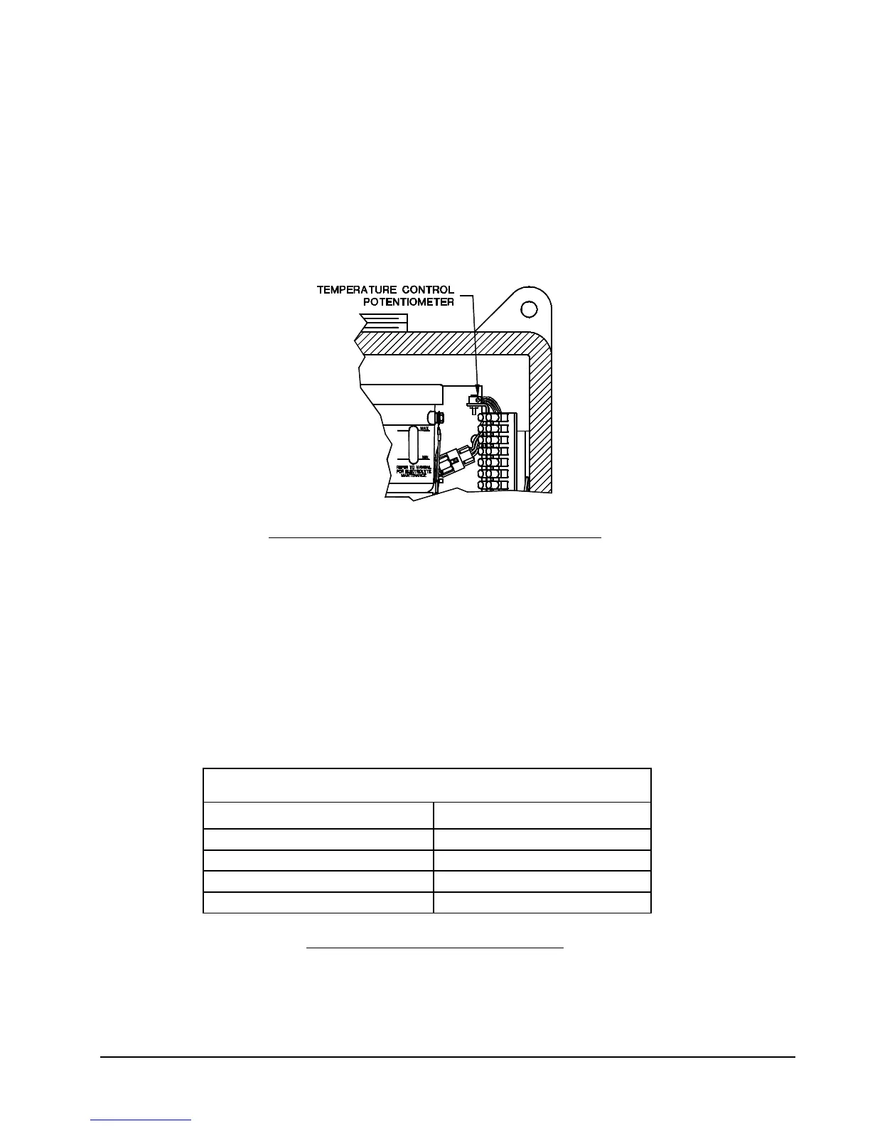
4) Locate the temperature control potentiometer on the circuit board in the enclosure above the
terminal strip. See Figure 28. Turn it clockwise to increase the temperature and counter-
clockwise to decrease it. After each adjustment re-cover the enclosure and allow at least an hour
for it to stabilize at the new temperature.
Figure 28: Temperature Control in R7 Enclosure
7.5.5 Remote Sensor Connections – Connector J7
There are three pair of connections that must be made between the oxygen sensor and connector
J7 on the electronics chassis. They are labeled SNSR + and -, SE + and – and TEMP + and -. It is
critical for optimum operation, and to prevent damage to the sensor, that the proper polarity be
maintained on all electrical connections. These connections should be made through a shielded,
twisted pair cable sized according to Table 11. The shield should be terminated only at the
Ground connection labeled GND on the same connector. To avoid ground loops, the shield
should be left open and not attached to the remote sensor chassis. See Figure 30 for wiring
connections.
Oxygen Sensor Cable Sizes
Distance in Feet Minimum Wire Size
0 – 150 #20 AWG
150 – 250 #18 AWG
250 – 350 #16 AWG
350 – 1000 #14 AWG
Table 11: Remote Sensor Cable Sizes