Options DF-310E 23
FILTER
SAMPLE INLET
1/8" COMPRESSION
232-GND
485-TX -
UNUSED
485-RX -
232-RX
232-TX
485-TX +
485-RX +
EXT-2 -
EXT+1 -
EXT-2 +
GND (H-)
SE -
SE+ (H+)
SNSR -
SNSR +
J7
UNUSED
TEMP -
TEMP +
UNUSED
UNUSED
LOOP -
J8
A4-NOA2-NO
EXT-1 +
FLOW-B
UNUSED
FLOW-A
UNUSED
PUMP +
PUMP -
A OUT -
A OUT +
GND
A4-NC
GND
UNUSED
LOOP +
UNUSED
J5
UNUSED
UNUSED
24V RTN
UNUSED
+24V
A2-NC
J3
GND
J6
J4
A4-COM
UNUSED
A3-NC
A3-NO
A3-COM
A1-NC
UNUSED
A2-COM
A1-NO
A1-COM
J1 J2
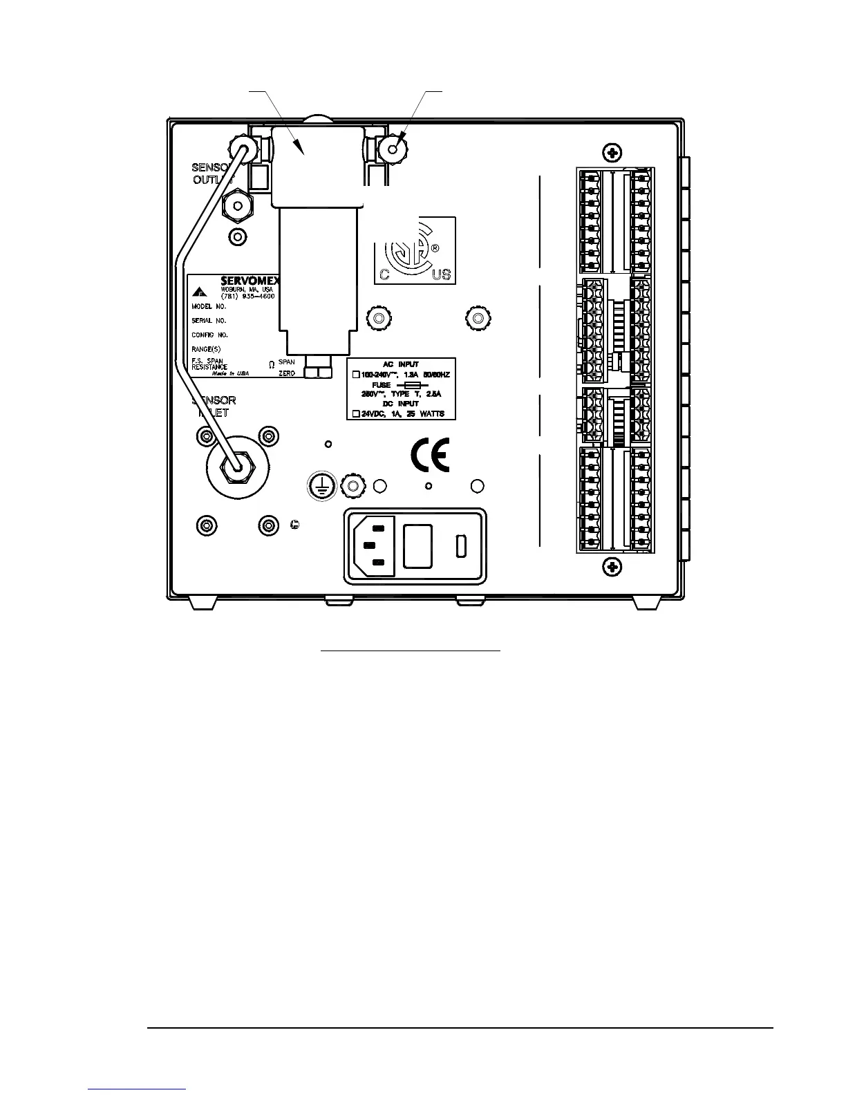
Figure 8: Filter Installation
5.7 Combined Filter/Pressure Regulator
The gas filter and regulator are installed by the factory when ordered with the
Analyzer. However, the gas filter and regulator may be ordered later and
installed by the user. They are supplied as a unit with one mounting bracket
and mounting screws. The option also includes a preformed tube with fittings
to connect the regulator outlet to the Analyzer inlet. These should be mounted
on the back panel as shown in Figure 3-4 using the supplied screws.
Note: The filter has two ports labeled 1 and 2. For particulate removal
plumb the filter with port 2 connected to the Analyzer's sample inlet fitting.
For mist coalescing and collection for draining, plumb the filter with port 1
connected to the Analyzer's sample inlet fitting.
NOTE: For additional information on the proper purging regulators after
installation see page 37