Plasma Gas Analyzer
27 02001001A_9
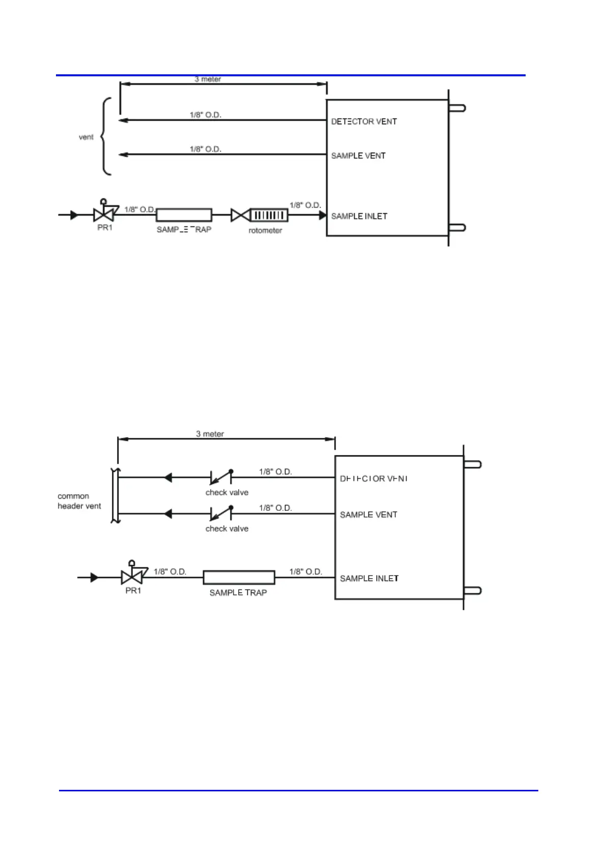
Figure 14 - POOR INSTALLATION EXAMPLE 2
Some users wish to monitor the inlet flow with a falling ball rotameter. Those rotameters (or
flowmeters) are calibrated at atmospheric pressure. The flow indicated will be wrong, it must
be compensated for the line pressure. Furthermore, these types of rotameters are absolutely
not leak tight. Air will diffuse into the system, there will also be some permeation through the
material used to build it. There is also a risk that someone tries to control the flow with the
valve mounted on this rotameter (if any). This will be in conflict with the analyzer internal flow
control system.
Problems caused: line pollution, flow instability, reading will be noisy, reading will definitely drift.
Figure 15 - POOR INSTALLATION EXAMPLE 3
Some users wish to avoid back flow from a vent header into the analyzer vent. Doing so will
cause sample flow and cell pressure variation. The cell pressure will follow header pressure
variation. Check valve cracking pressure is not constant. The plasma cell must work at
atmospheric pressure with no backdraft. Problems caused: noisy signal, risk of cracking the
cell on the event of check valve failure.