ShopBot PRS Assembly Manual Page -2
PRSAssembly080922.doc Copyright 2007,2008 ShopBot Tools, Inc
Contents
Assembly Manual .................................................................................................... 1
Table Surface Considerations..........................................................................................................................3
Electrical Precautions ......................................................................................................................................4
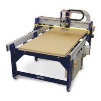
Overview of Your ShopBot PRS CNC Tool......................................................................................................5
Assembling Your ShopBot...............................................................................................................................7
Tools You Will Need..........................................................................................................................7
Unpacking and Getting Your Work Area Organized: .........................................................................8
Connection to Electrical Service ......................................................................................................................9
Overview of the Assembly Process ...............................................................................................................10
Off and Running….........................................................................................................................................10
Assembling the Table ............................................................................................. 11
Table Parts............................................................................................................ 12
Assembly Steps ..................................................................................................... 14
Step1.1: Attach a Machine Glide to the Bottom of Each of the Table Legs....................................................14
Step 1.2: Attach the Table Legs to the Table Sides.......................................................................................14
Step 1.3: Attach the First Upper Table Support .............................................................................................16
Step 1.4: Slide the Cross Supports into Position ...........................................................................................18
Step 1.5: Working on the other End of the Table where the Legs are still temporarily attached to the Outside
of the Table Sides..........................................................................................................................................19
Step 1.6 Square and Level Table .............................................................................. 20
Table Surface (probably attach later?) ...................................................................... 21
Suggested Materials ......................................................................................................................................21
Attaching the Table Surface...........................................................................................................................21
Installing the Gantry .............................................................................................. 23
Installing the X-Rails and Getting One Rail Straight..................................................... 23
Slide the X-Rails onto the Table ....................................................................................................................23
Set the Front Side X-Rail and Check for Straightness...................................................................................23
Adjust the Position of the Rear X-Rail............................................................................................................24
Putting the X-Car on the Rails and Using it to Align the Rear X-Rail ............................... 25
Lower the X-Car onto the X-Rails ..................................................................................................................25
Use the X-Car as a Guide to Align the Rear X-Rail .......................................................................................26
Mounting the YZ-Car and adjusting its lower wheel bearings ........................................ 27
Place YZ-Car on the X-Car............................................................................................................................27
Attach the Lower Wheel Bearings on the YZ-Car ..........................................................................................28
Adjust the Lower Wheel Bearings on the YZ-Car ..........................................................................................29
Attaching the Motors .............................................................................................. 30
Put the Pinion Gears on the Motors...............................................................................................................30
Mount the Motors...........................................................................................................................................31
Set the Mechanical End Stops for the X Axis.................................................................................................33
Run the X-2 Motor Cable through the Aluminum Beam.................................................................................34
Mounting the Router or Spindle................................................................................ 35
If You Have a Porter Cable Router ................................................................................................................35
If You Have a High Frequency Spindle:.........................................................................................................36
After Mounting the Router/Spindle............................................................................ 37
Wheel Guards........................................................................................................ 37
Proximity Switches................................................................................................. 38
Install the Proximity Switches ........................................................................................................................38
Y-axis Targets................................................................................................................................................39
X-Axis Targets. ..............................................................................................................................................40
Z-Zero Plate Holster ............................................................................................... 40
PRS Y-axis EChain Installation ................................................................................. 41
Secure cables and wiring......................................................................................... 46
Run the YZ Wiring .........................................................................................................................................49
Neaten up the Wiring at the Back Side of the X Car ......................................................................................49
Create a Cable Loop on the way to the Control Box......................................................................................49
Hooking Up to the Control Box ................................................................................. 50
Do’s and Don’ts ..................................................................................................... 50