ShopBot PRS Assembly Manual Page -53
Explore the PRSalpha Control Box
After the electrician has hooked up your PRSalpha Control Box
and router or spindle, it’s time for you to get involved again. The
electrician is not expected to know how to hook-up the tool itself
to the PRSalpha Control Box. That process is covered in the
following instructions.
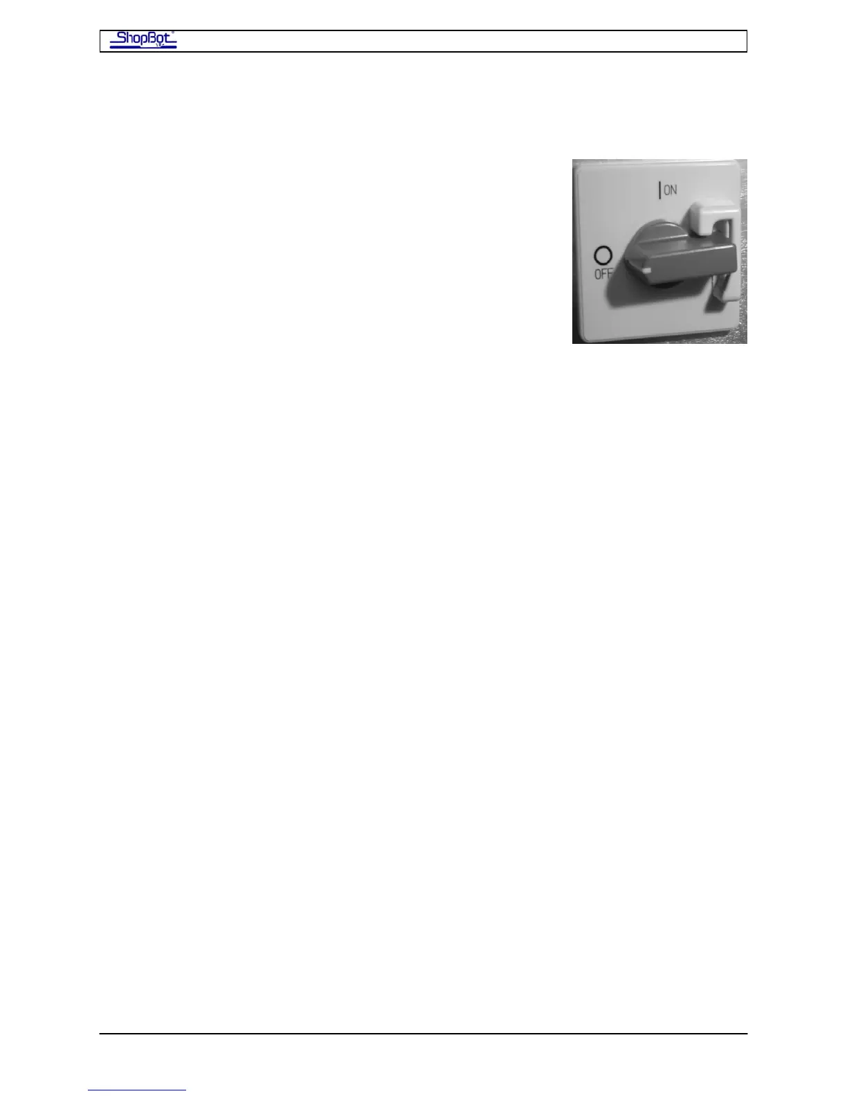
Disconnect electrical power to the PRSalpha Control Box.
Open the side of the box with a screwdriver (quarter turn). Note
that the door cannot be opened or closed unless the switch is
turned off.
Refer to the labeled picture of the PRSalpha Control Box on the next page.
The Contactors, located at the top of PRSalpha Control Box, are the large relays that control
power to the equipment. They are controlled by the e-Stop and by software. The size of the
contactor may vary with the power requirements of the device it is powering. Additional
contactors for additional devices (example, second router or spindle) are added to the left of
the standard contactors.
The Fuses in the PRSalpha Control Box (US 60Hz power) are dependent upon the setup:
Porter Cable router (single): 1 30A fuse, 1 15A fuse
Porter Cable routers (two): 1 30A fuse, 2 15A fuses
Colombo Spindle: 1 30A fuse, no other fuses (Colombo protected by fused disconnect before
the PRSalpha Control Box.)
Troubleshooting: Although the fused disconnect should protect the PRSalpha Control Box, if
you lose power to everything in the PRSalpha Control Box, please check the fuses and
replace if necessary.
PRSAssembly080922.doc Copyright 2007,2008 ShopBot Tools, Inc