ShopBot PRS Assembly Manual Page -62
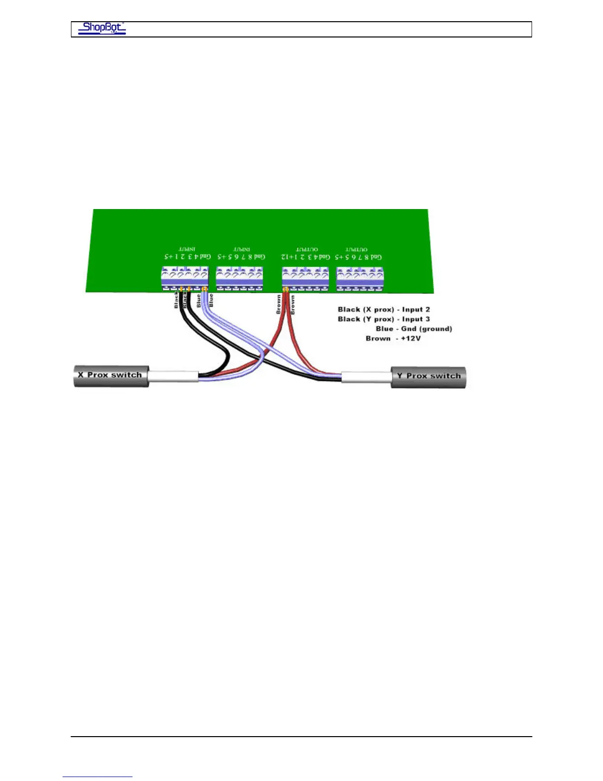
Connect the Cables from the Proximity Switch and Z-zero Plate
Inside the PRS Standard Control Box, take the Proximity Switch cable for the X-axis and
place its black wire into Input 2 on the blue terminal block on the control board. Then take
the Proximity Switch cable for the Y-axis and place its black wire into Input 3 on the same
blue terminal block on the Control Board. The blue wires from both of the switches are
placed in Gnd (ground). The brown wires from both of the switches will be placed in the
+12V position on the blue Output terminal block. Remember that the terminal blocks can be
removed to make wire insertion easier.
When the PRS Standard Control Box is powered up, a red LED in the body of the proximity
switch out on the tool will stay bright until it is triggered by coming near a target.
Now also plug in the Z-zero plate. The black wire goes in the Input#1 terminal and the
white (or green) wire goes into a ground terminal (Gnd; you can use the one on the Input
terminal block or the one on the Output block). The red wire goes to 5+ (it is only used by
the Digitizing Probe).
There is USB cable connector for attaching the USB cable that will connect your PRS
Standard Control Box to your computer. It is a short cable that exits on the right side of the
Control Board. Plug the longer 10ft cable supplied with your ShopBot into this connector. Do
not plug the USB cable into your computer at this point.
Ground the ShopBot PRSstandard
The ShopBot Table should be grounded to System Ground at the power box that supplies
the PRS Standard Control Box. Attach the grounding wire (14-16 gauge) at a convenient
bolt on the table, making sure to scratch off paint under the bolt.
Remember that your dust collection system should also be grounded to the System Ground.
See alpha Dust Skirt Documentation for details on grounding the alpha Dust Skirt hoses to
the Dust Collection device.
PRSAssembly080922.doc Copyright 2007,2008 ShopBot Tools, Inc