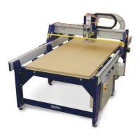
ShopBot PRS Assembly Manual Page -61
Hooking Up Your PRSstandard
Plug the Motor Cables into your PRS Standard Control Box
Remember the earlier warning…your PRS Standard Control Box should now be turned off
and unplugged, correct?
Lay the PRS Standard Control Box down on its side (connectors down) and remove the two
screws holding on the right side panel. Pull off the side so that you can work on the Control
Board.
As you are plugging the motors wires into the PRS Standard Control Box, note that the
connectors are keyed and will only fit one way. Make sure they are fully inserted and locked
into position.
• The X1 (single red tape) motor cable goes into the connector at the top of the driver
board visible at the back of the PRS Standard Control Box labeled X1.
• The X2 (double red tape) connects into the X2 connector, second from top.
• The Y (blue tape) cable goes into the Y connector, third from top.
• The Z (white tape) cable plugs into the Z connector, fourth from top.
• A second Z motor (yellow tape) plugs into the A driver connector, bottom.
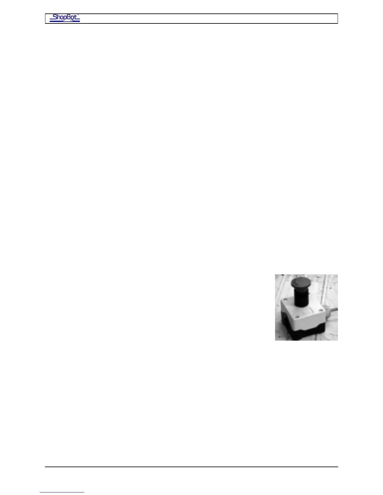
Connect the Cable from the Remote-Stop Switch
The PRSstandard comes with a Remote Stop Switch (Stop). Hitting
this ‘Stop’ button will immediately stop the motion of your
PRSstandard tool and keep it stopped until the switch is unlocked.
Power to the electrical cutter on your ShopBot is NOT turned
off by this button.
At the very back of the board, you will see 4 blue connectors with screw terminals. These
blue connectors can be removed to install wires…just pull straight up on them. After you’ve
made the connections, carefully place the wires back in the same position. Notice that the
terminals are labeled on the circuit board underneath.
The 2 blocks towards the bottom of the box are the connectors for ‘Inputs’. The 2 toward
the top are for ‘Outputs’. At this time, we will just be dealing primarily with the Input plugs.
The Stop button has two, normally closed switches (white/red; black/green). We will wire in
only one switch using the black and white (was green in older models) wires.
The white wire from the Remote-Stop is connected to the Ground connection at the left side
of the Input connector. The Black wire is connected to Input terminal #4, which corresponds
to Input Switch #4 in your ShopBot Software. Using a tiny screw driver, snug up the wires
into the correct location.
PRSAssembly080922.doc Copyright 2007,2008 ShopBot Tools, Inc