Connecting the encoder
50 ATM60-Cxx 03/2007
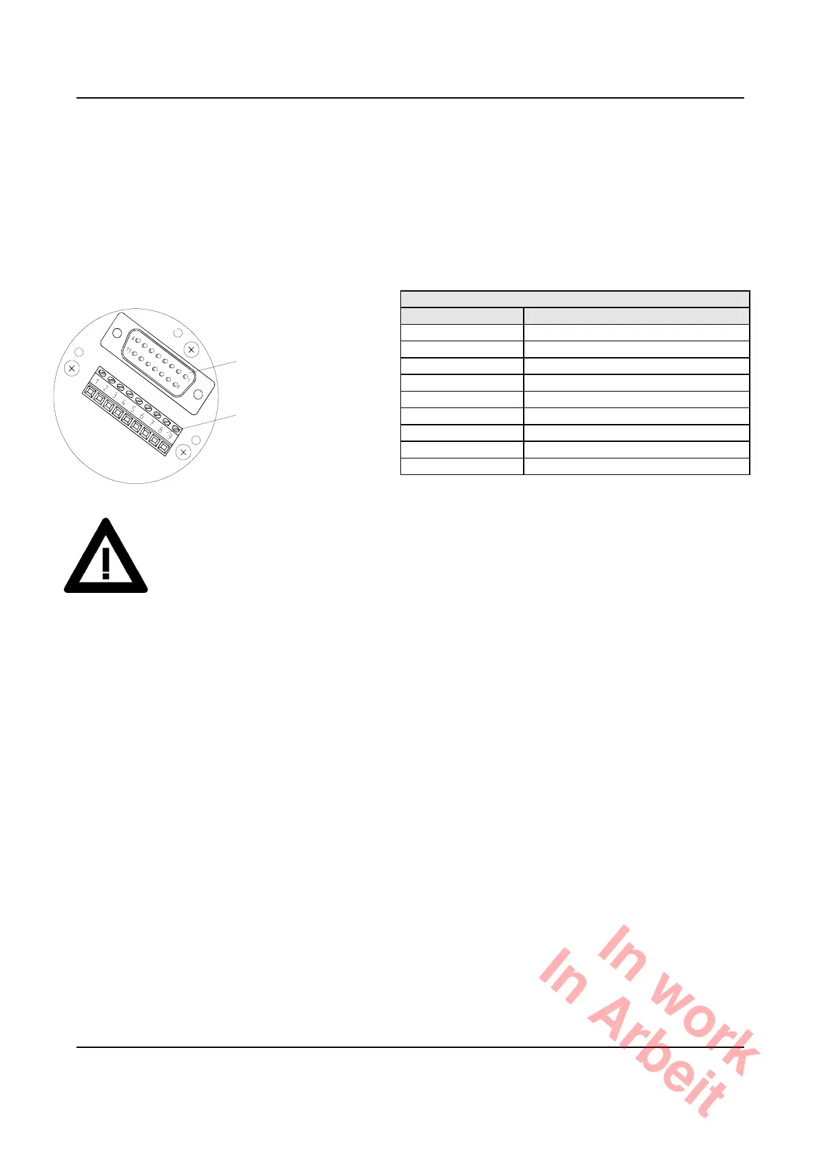
12.6 Pin allocation
12.6.1 Bus connector with PG screw fittings
In order to connect the bus lines and the supply, the bus connector must be removed. For this purpose, the
three screws on the rear of the bus connector have to be unscrewed. The terminal strip described below
becomes accessible.
9-way terminal strip
with bus-connector
Signal Explanation
housing unscrewed
US Supply voltage 10 .. 32V
GND Earth
encoder-side connection
CAN
L
CAN bus signal low
CAN
H
CAN bus signal high
CAN
L
CAN bus signal low
CAN bus
CAN
H
CAN bus signal high
connection
US Supply voltage 10 .. 32V
GND Earth
Shield Screen connection
After the leads have been connected, the bus connector should be mounted on the encoder
housing again, attention having to be paid to the correct seat of the seal (O-ring on the encoder
housing and sealing washers under the housing screws).
In work
In Arbeit

 Loading...


