Operating Instructions Chapter 3
C4000 Select
8012247/RI61/2007-11-30 © SICK AG • Industrial Safety Systems • Germany • All rights reserved 15
Product description
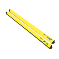
There are two methods of implementing C4000 Select cascades. The first method utilizes
a
n extended I/O connection located on the top end cap for the first C4000 Select (host)
and the second C4000 Select (guest 1). The third C4000 Select (guest 2) utilizes a system
connection only.
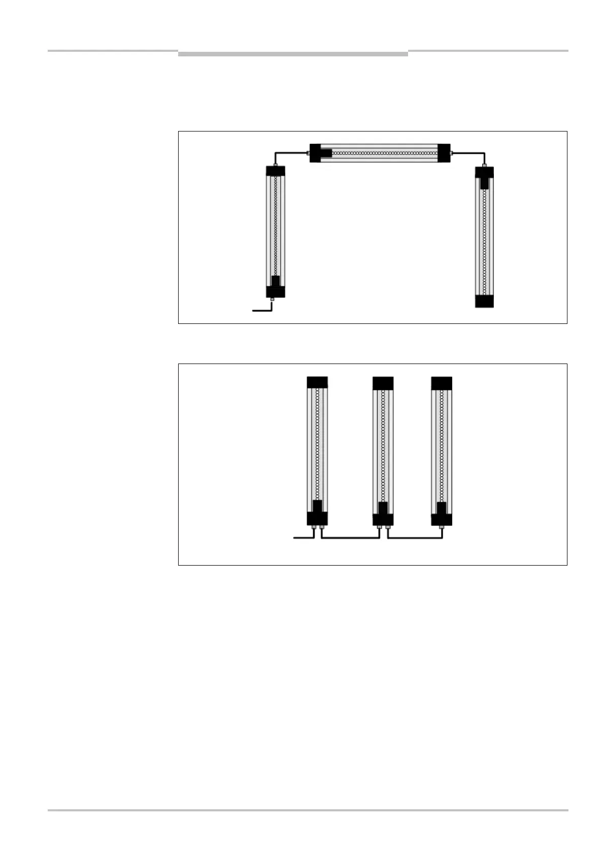
Alternatively, the second method of implementing cascaded C4000 Select devices uses an
extended I/O connection that is located on the same end cap as the system connection.
Sender units cannot be physically connected to receiver units when cascading C4000
Select devices. Always physically connect sender units together when cascading. Always
physcially connect receiver units together when cascading C4000 Select devices.
vers used in cascade with
extension connection (on top
end cap)
vers used in cascade with
extension connection (on
same end cap as system
connection)
Note