Product Description
14 FLOWSIC600 · Operating Instructions · 8010458 V2.0 · © SICK MAIHAK GmbH
2.1
System Components
The FLOWSIC600 measuring system consists of the following hardware components:
● Meter body
● Ultrasonic transducers
● Signal processing unit SPU
The MEPAFLOW600 CBM software is the user interface used to facilitate operation,
configuration and diagnosis (see
→
pg.20, 2.3).
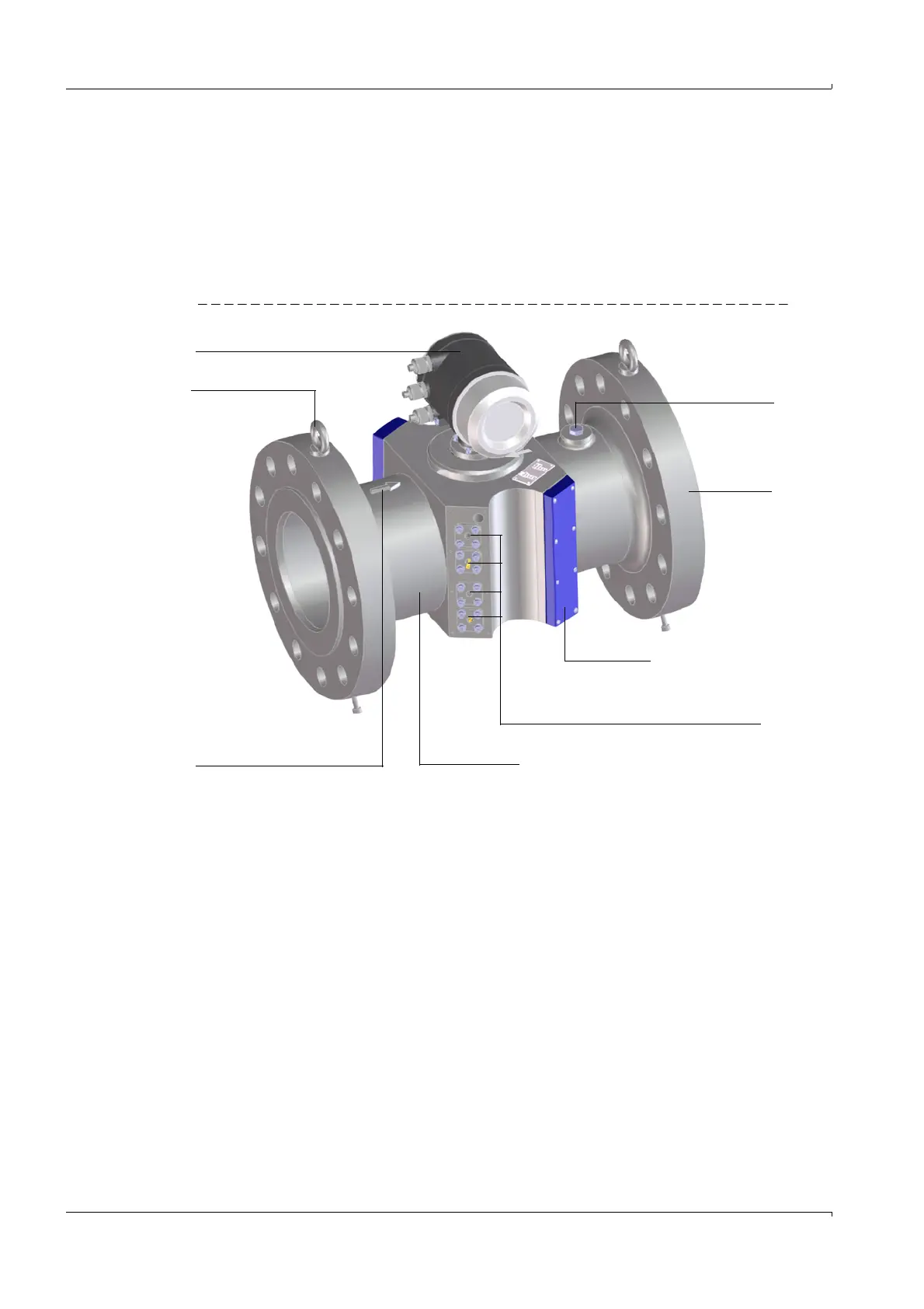
Figure 1 FLOWSIC600
2.1.1
Meter body
The meter body consists of a mid section for mounting the ultrasonic transducers, with
flanges on either end. For meter sizes up to 24“, the body is made of a single-piece casting,
which is machined on precision equipment to ensure high reproducibility of the geometric
parameters. For meters larger than 24“ the body is made of a single-piece casting or
forged or the flanges are welded onto the machined mid section.
The internal diameter, design of the sealing surface, and standard dimensions of the
flanges are in accordance with the specifications in the key code. The meter body material
is chosen to suit customer requirements. Standard meter bodies are available in carbon
steel, Low Temperature Carbon Steel and stainless steel.
The meter bodies can be delivered in several nominal sizes (see
→
pg.82, 7.1.3).
Meter body
Cover cap
Pressure tap
Flange
SPU
Hoisting eye
Position of the ultrasonic transducers
(cover cap taken off)
Marking for direction of
flow (forward)