internal
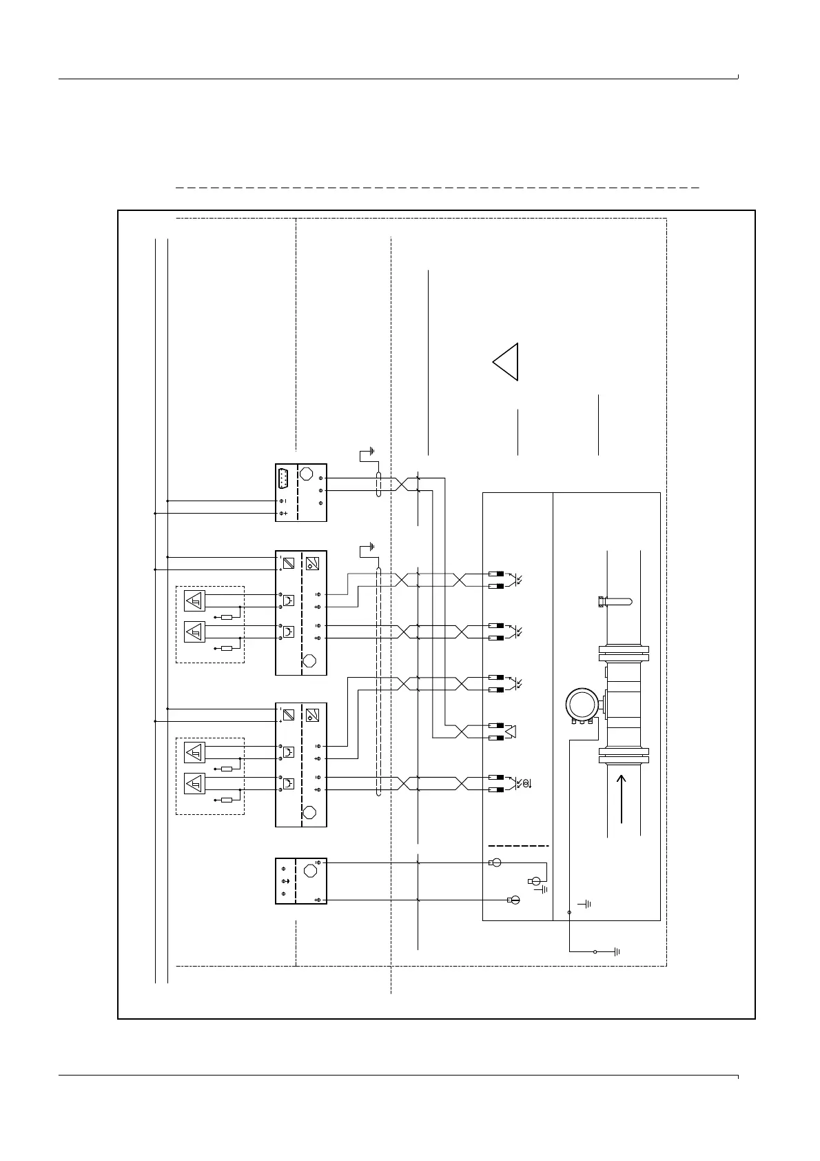
Non Hazard Area
.
<= 24V DC
<= 24V DC
R
L
R
L
<= 24V DC
<= 24V DC
R
L
R
L
24V DC +
24V Gnd
shield
RS 485
Ex
[EEx ib] IIC
RS 232
24VDC
STAHL 9185
RxD T xD
Service
Interface
Modbus
Volume pulse
Status
Status
Explosion Hazard Location
Intrinsic savety circuits
Non Intrinsic savety circuits
AO 0
DO 0
FLOWSIC 600
RS 485
DO 1
DO 2
DO 3
Class1, Division1, Groups B, C and D
Class1, Division2, Groups A, B, C and D
Class1, Zone 1 Group IIB + Hydrogene
Class1, Zone 2, Group IIC
II 1/2G EEx de ib [ia] IIC T4 or
II 1/2G EEx de ib [ia] IIA T4
31+
32-
33+
34-
51+
52-
41+
42-
81+
82-
1 (+)
2 (-)
FL600
Li2YCYv(TP)
4x2x0,5 mm²
ScreenScreen
(TP) - Twisted pair
NYY-O
2 x 1,5 mm²
Li2YCYv(TP)
2x0,5 mm²
in EU in accordance with EN 60079-14
National regulation must be observed.
maximum length: 100 m
RS485 Modbus - approx. impedance 120 Ohm
1/2" NPT (North America)
6 - 12 mm cable diameter
Attention:
!
WARNING!
Incorrect cabling can cause
the FLOWSIC 600 to fail!
For further details see
operation manual.
Cable glands
Intrinsic savety installation:
in accordance with
in North America
NEC and CEC, see
Control Drawing 781.00.02
Compliance CSA 1298901
EC-Typ-Examination Certificate
For Savety/Entity - Parameters see
TÜV 01 ATEX 1766 X resp. Certificate of
M20 x 1,5 (EU) or
or 4 .. 20 mA passiv
Volume pulse
Remark:
Flowcomputer
SICK recommends to connect all signals
of FLOWSIC 600 with cabels to the non
hazardous area.
Ex
24VDC
[EEx ia] IIC
1+
4-
2+
5-
8+
9-
11
12
10-
7+
MK13-22EX0-T/24VDC
Ex
24VDC
[EEx ia] IIC
1+
4-
2+
5-
8+
9-
11
12
10-
7+
MK13-22EX0-T/24VDC
[EEx ib]
L N
Ex
9143
STAHL
10
11
STHAL power supply
9143/10-156-160-10s