FLOWSIC600 · Operating Instructions · 8010458 V 2.0 · © SICK MAIHAK GmbH 27
Installation
3.2.2
Installation configurations
The choice of the installation configuration (see
→
Figure 6 and
→
Figure 7) depends on type
and extent of the flow disturbance at the installation position (according to TR G13).
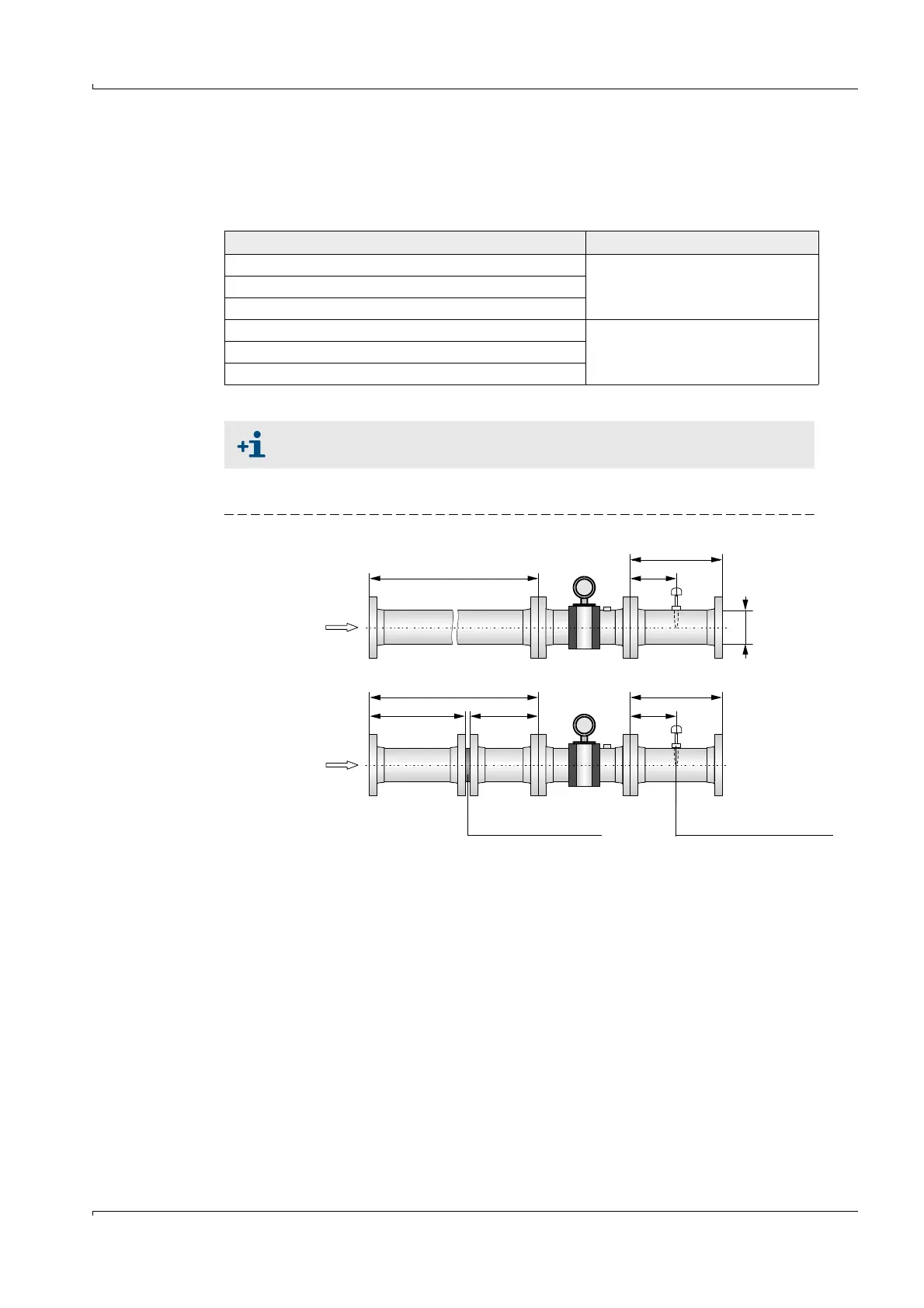
Unidirectional use
Figure 6 FLOWSIC600 installation in the pipeline for unidirectional use
Type of disturbance (distance upstream < 20 DN) Possible installation configuration
None Configuration 1 or 2
Elbow, reducer
Double elbow out of plane, T piece
Gas pressure controller with/ without noise abatement trim Configuration 2
Diffuser
Diffuser with swirling flow
When configuration 2 (with flow conditioner) is used, the velocity of gas must
not exceed 40 m/s (131 ft/s) in the pipe.
≥ 3 DN
min. 2 DN min. 2 DN 1.5 .. 5 DN
Flow conditioner Temperature measuring point
Configuration 1
Configuration 2
≥ 10 DN 1.5 .. 5 DN
FLOWSIC600 ≥ 3 DN
DN
≥ 5 DN