.
-X
.
. .
L
R
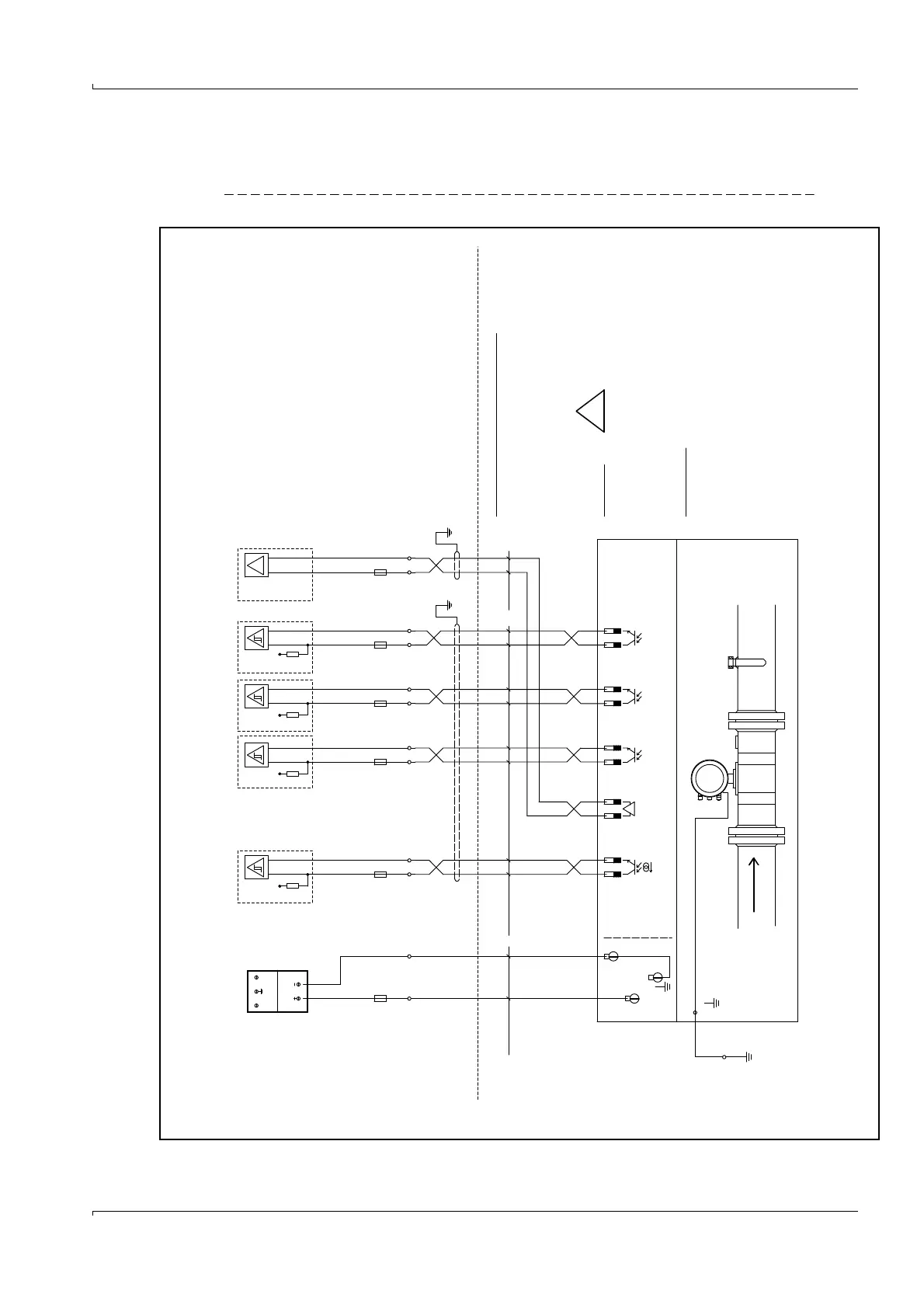
Imax = 100 mA
super fast
100 mA
fast
1A
internal
Fuse
Fuse
24 V DC
Non Hazard Area
Volume pulse
Hazard LocationExplosion
or 4 .. 20 mA
Status
..
Fuse
Imax = 100 mA
R
L
..
Fuse
Imax = 100 mA
R
L
. .
Fuse
Imax = 100 mA
R
L
Modbus
Status
<= 24V DC
<= 24V DC
<= 24V DC
<= 24V DC
super fast
100 mA
super fast
100 mA
L N
24 VDC
.
AO 0
DO 0
FLOWSIC 600
RS 485
DO 1
DO 2
DO 3
Class1, Division1, Groups B, C and D
Class1, Division2, Groups A, B, C and D
Class1, Zone 1 Group IIB + Hydrogene
Class1, Zone 2, Group IIC
II 1/2G EEx de ib [ia] IIC T4 or
II 1/2G EEx de ib [ia] IIA T4
31+
32-
33+
34-
51+
52-
41+
42-
81+
82-
1 (+)
2 (-)
FL600
NYY-O
2 x 1,5 mm²
. .
100 mA
super fast
Li2YCYv(TP)
2x0,5 mm²
Li2YCYv(TP)
4x2x0,5 mm²
(TP) - Twisted pair
Fuse
Screen
Attention:
6 - 12 mm cable diameter
1/2" NPT (North America)
RS485 Modbus - approx. impedance 120 Ohm
maximum length: 100 m
Cable glands
operation manual.
For further details see
the FLOWSIC 600 to fail!
Incorrect cabling can cause
WARNING!
!
in EU in accordance with EN 60079-14
National regulation must be observed.
Volume pulse
in North America
Non intrinsic installation:
see control drawing 781.00.02
in accordance with NEC and CEC,
M20 x 1,5 (EU) or
Flowcomputer/Systemcontroller
Fuses for field terminals:
Very fast acting type (FF-Type)
In case of blow out lock for reason
before change.
Additional surge protection is
recommended in case of powerful or
recurrent strokes of lightning.
Remark:
SICK recommends to connect all signals
of FLOWSIC 600 with cabels to the non
hazardous area.