FLOWSIC600 · Operating Instructions · 8010458 V 2.0 · © SICK MAIHAK GmbH 39
Installation
3.4.6
Operation in hazardous areas (Directive 94/9/EC (ATEX)
1
)
The power supply and field connections are designed with the increased type of protection
(“e“). The transducer connections are of an intrinsically safe design (“ia“).
All screw-type terminals as well as air gaps and creepage distances of the FLOWSIC600
comply with EN 60079-7.
Connection characteristics
Connection options
The protection concept for the FLOWSIC600 permits the following connection options:
● Non intrinsically safe power supply connection and field connections with increased
type of protection (“e“)
● Intrinsically safe power supply connection and field connections (“i“)
● Non intrinsically safe power supply connection with increased type of protection (“e“),
while the field connections are intrinsically safe (“i“)
The user shall decide which option is to be used, taking into account local / national
regulations and standards or EN 60079-14.
A combination of intrinsically safe and non-intrinsically safe circuits is not permitted in the
terminal box for the field connections.
The rated voltage of non-intrinsically safe circuits is U
M
= 253 V.
1 For use in the US and Canada see Control drawings 781.00.02 page 1 to 3.
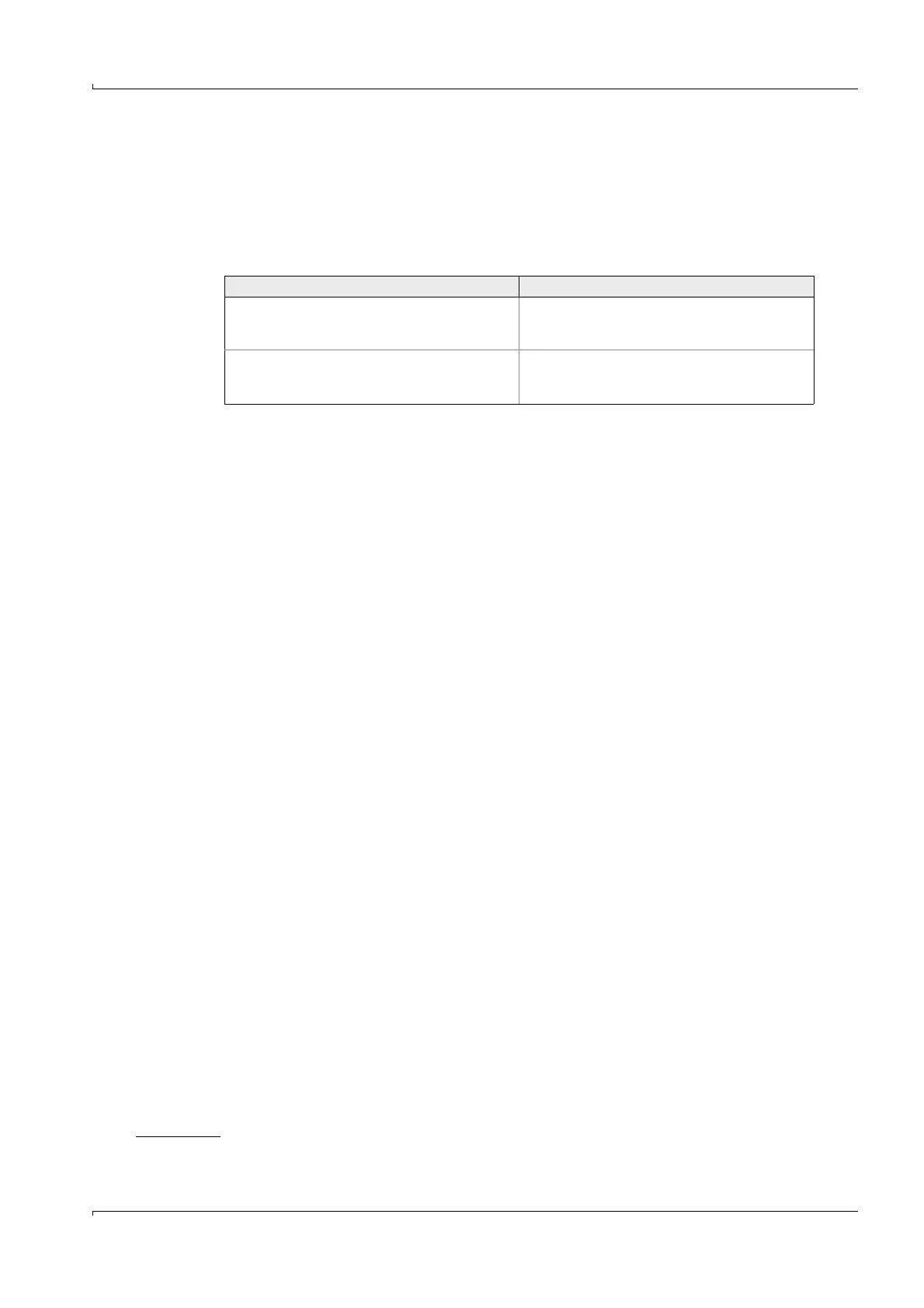
Power supply connection Field connections
Separate terminal box, separated from the field
connections with partition wall in the housing
and cover to EN 60079-11.
Separate terminal box, separated from the
power supply connections with partition wall in
the housing and cover to EN 60079-11.
Cable routing via Exe cable gland, M5 ground
terminal integrated into housing section (cast-on
part).
Cable routing via 2x Exe cable gland