FLOWSIC600 · Operating Instructions · 8010458 V 2.0 · © SICK MAIHAK GmbH 15
Product Description
2.1.2
Ultrasonic transducers
The FLOWSIC600 ultrasonic transducers are optimized to suit the application
requirements. The high quality of the transducer design provides the basis for accurate
and highly stable propagation time measurements with nanosecond precision. These
transducers are of an intrinsically safe design (category “ia“).
2.1.3 Signal processing unit
The SPU contains all the electrical and electronic components for controlling the ultrasonic
transducers. It generates transmission signals and analyzes the received signals to
calculate the measuring values. The SPU also contains several interfaces for
communication with a PC or standardized process control system.
The volume counters, errors, warnings, and system events are stored in a non volatile data
memory (FRAM) together with a time stamp (Logbooks
→
pg.86, 7.2.) On system restart, the
counter readings that were last saved are restored as the start values for the volume
counters. The FRAM backup provides an unlimited number of writing cycles and protects
the saved data for at least 10 years.
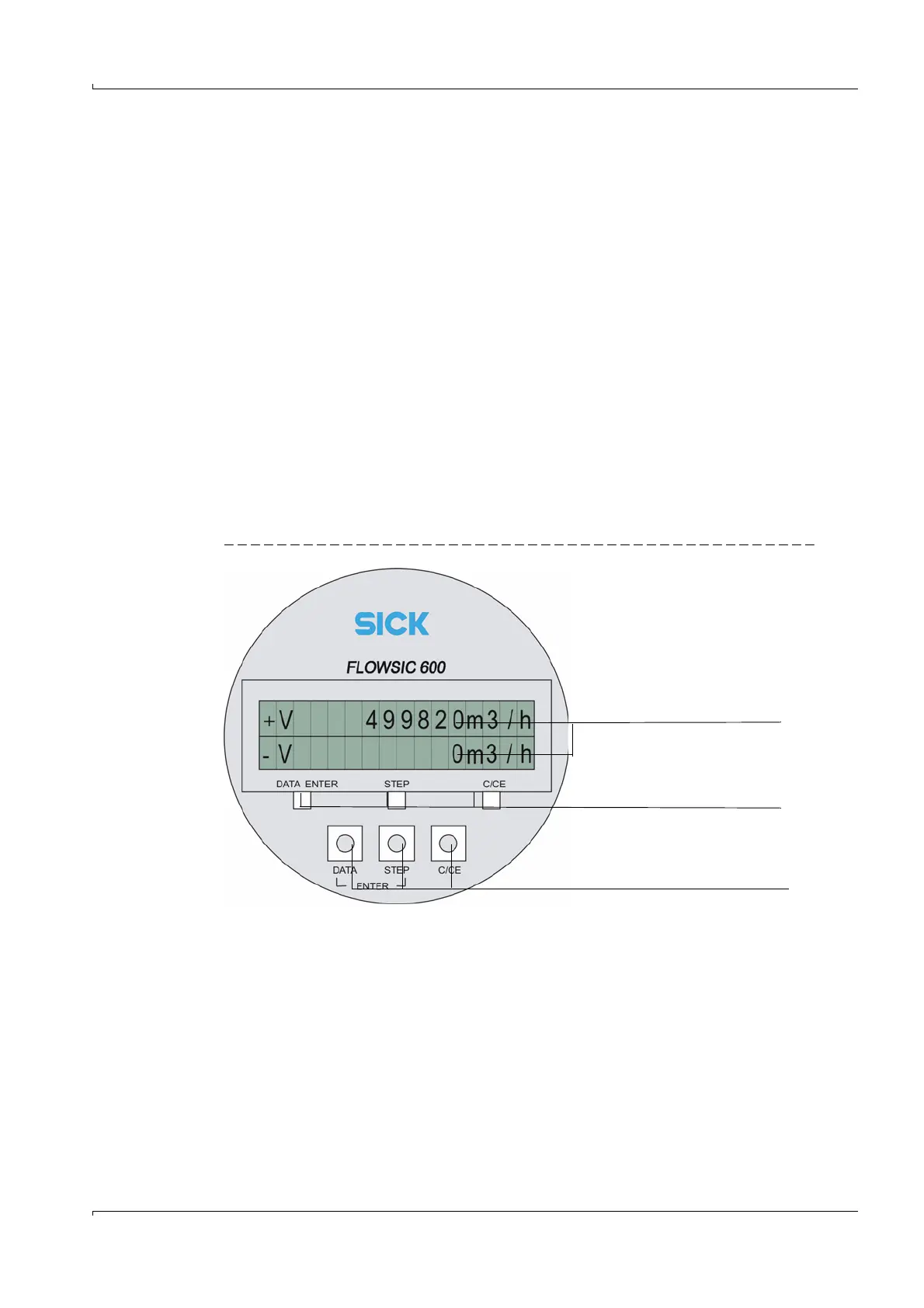
The SPU is equipped with a front panel containing a two-line LCD to display current
measured values, diagnostics and logbook information (
→
Figure 2). The values to be
displayed can be selected using a magnetic pen without removal of the front cover . The
MEPAFLOW600 CBM software provides a more user-friendly way to display the information.
Figure 2 FLOWSIC600 front panel LCD
The power supply and interface terminals are located on the back of the SPU in a separate
terminal section of the enclosure (
→
pg.36, 3.4.4).
The electronics are mounted in the SPU enclosure certified to EN 60079-1 or IEC 60079-1
with protection type “d“ (flameproof enclosure). The transducer circuits are of an
intrinsically safe design (category “ia“).
Measured values
Control buttons for the magnetic pen
Control buttons for manual use